This project I started on a leisure weekend some time ago. The time is now to document it. Always wanted to measure the bandwidth of my two oscilloscopes, an analog and a digital one. There is help from the avalanche breakdown. During this type of breakdown, free carriers in the p-n transition region are exponential multiplied, leading to a rapid current rise. In other words, you can generate pulses with a very short rise time.
Idea
The idea I got from this article: Avalanche Pulse Generator Build Using 2N3904. The circuit is very simple but needs at least 120V to operate. Blessedly is no exotic component included like an avalanche-diode. Many standard transistors you may have in your junk box can be used for the avalanche breakdown. I found some 2N3904. Suddenly cutted a piece of breadboard, collected the remaining components and heated the soldering iron.
Circuit
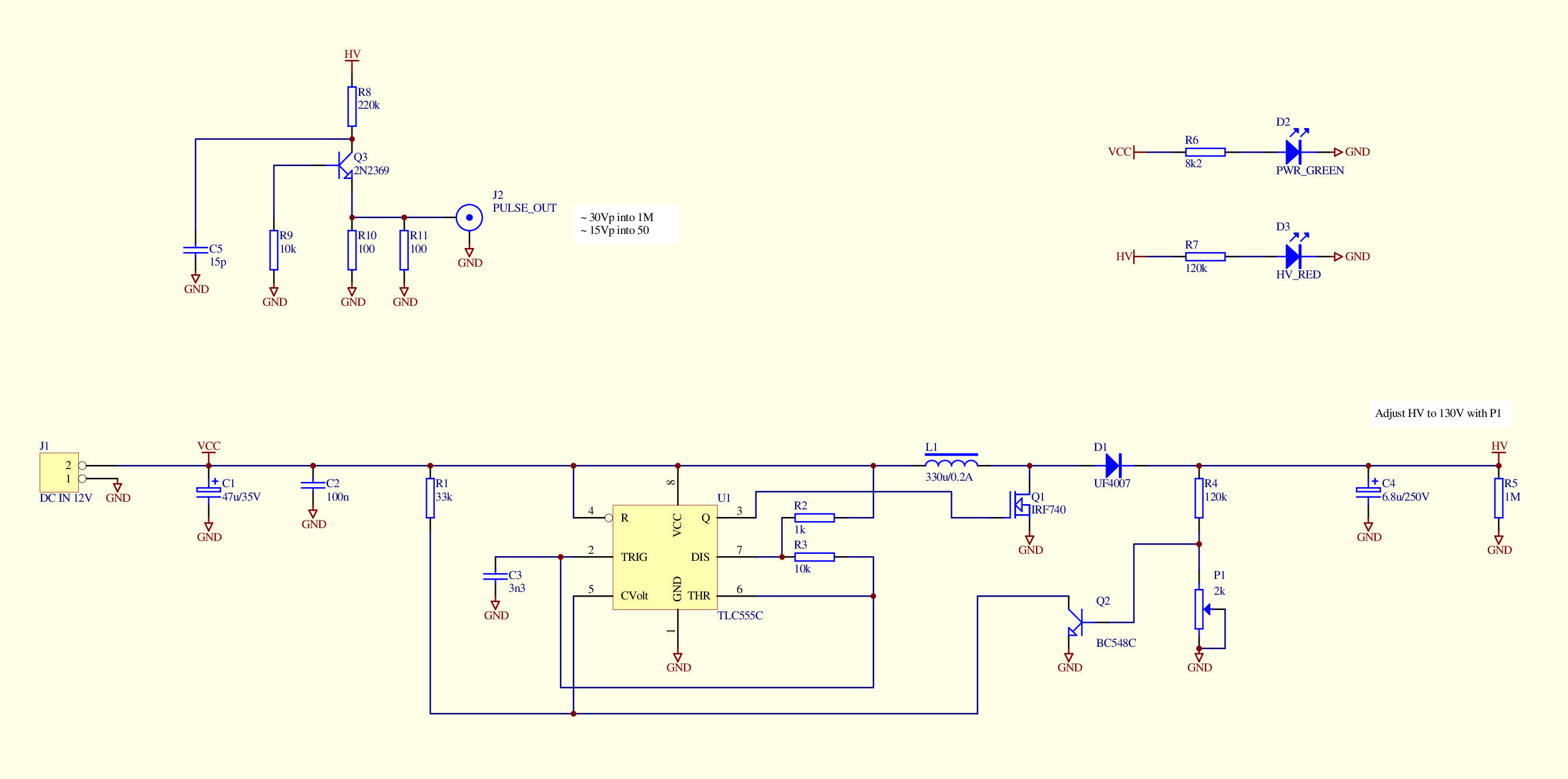
A old-school 555 timer IC acts as high voltage generator, a circuit I used several times before, for instance in the VU-Meter with EM84. The avalanche pulse generator itself is composed of only six components as you can see in the schematics diagram.
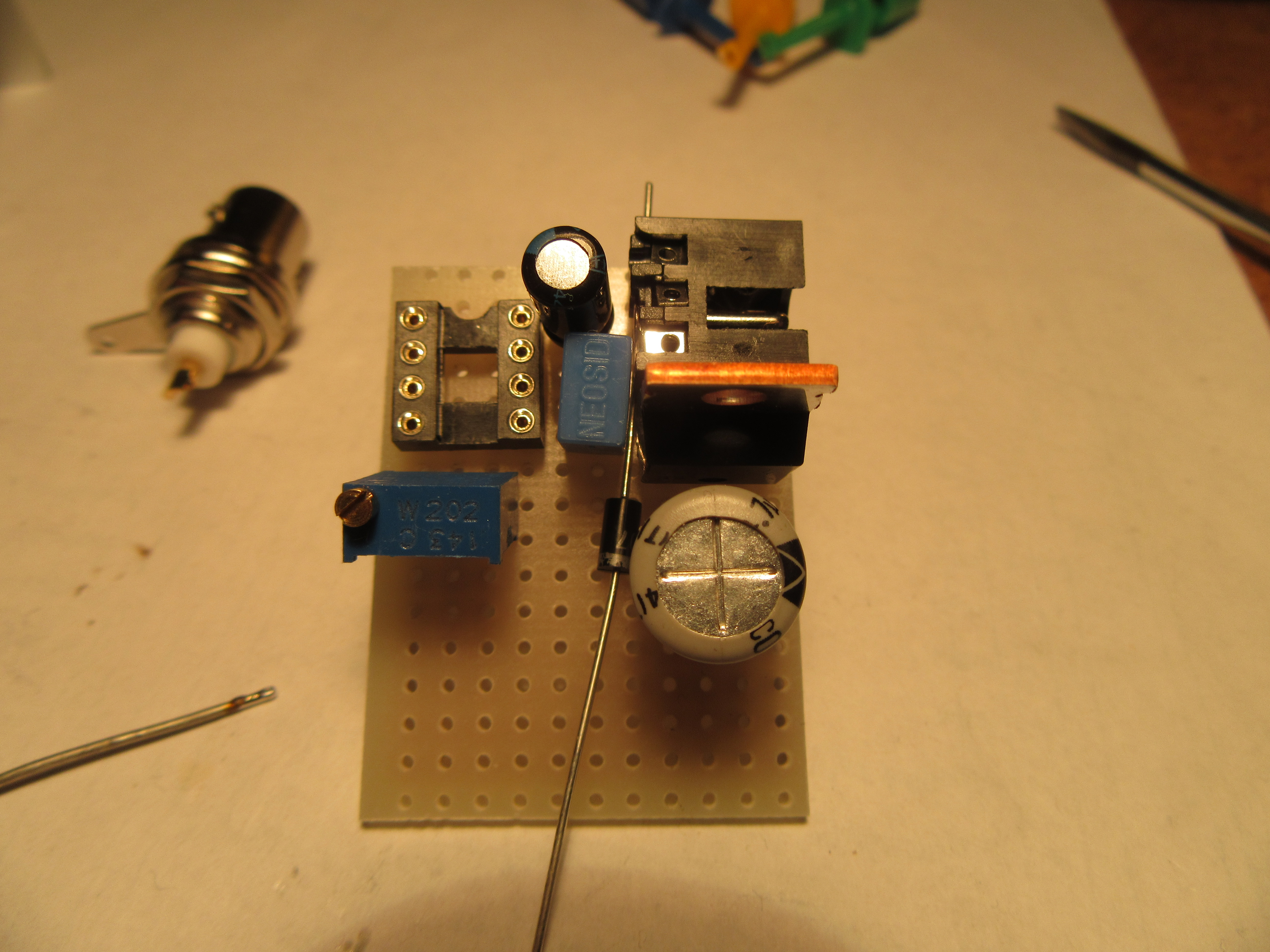
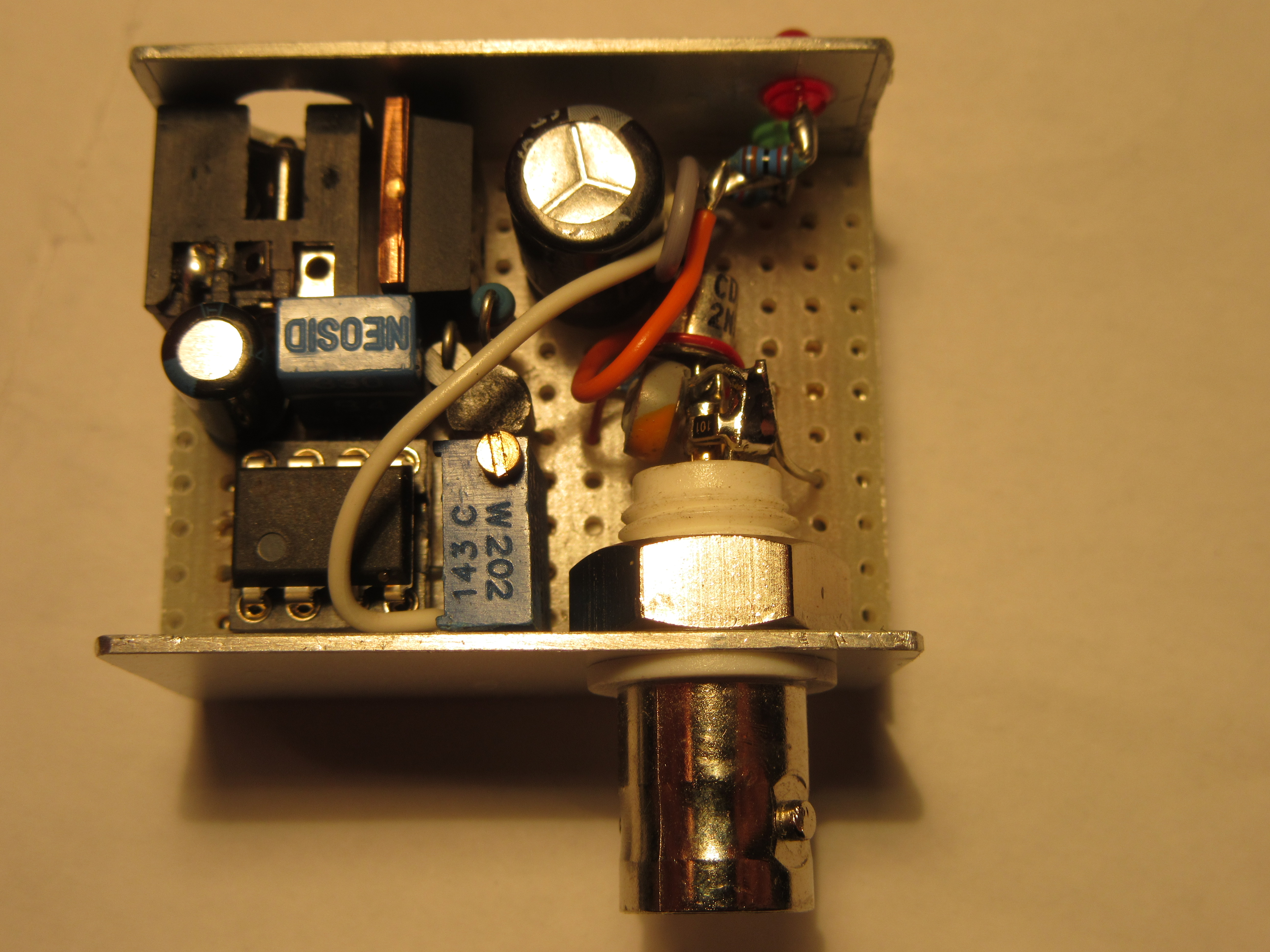
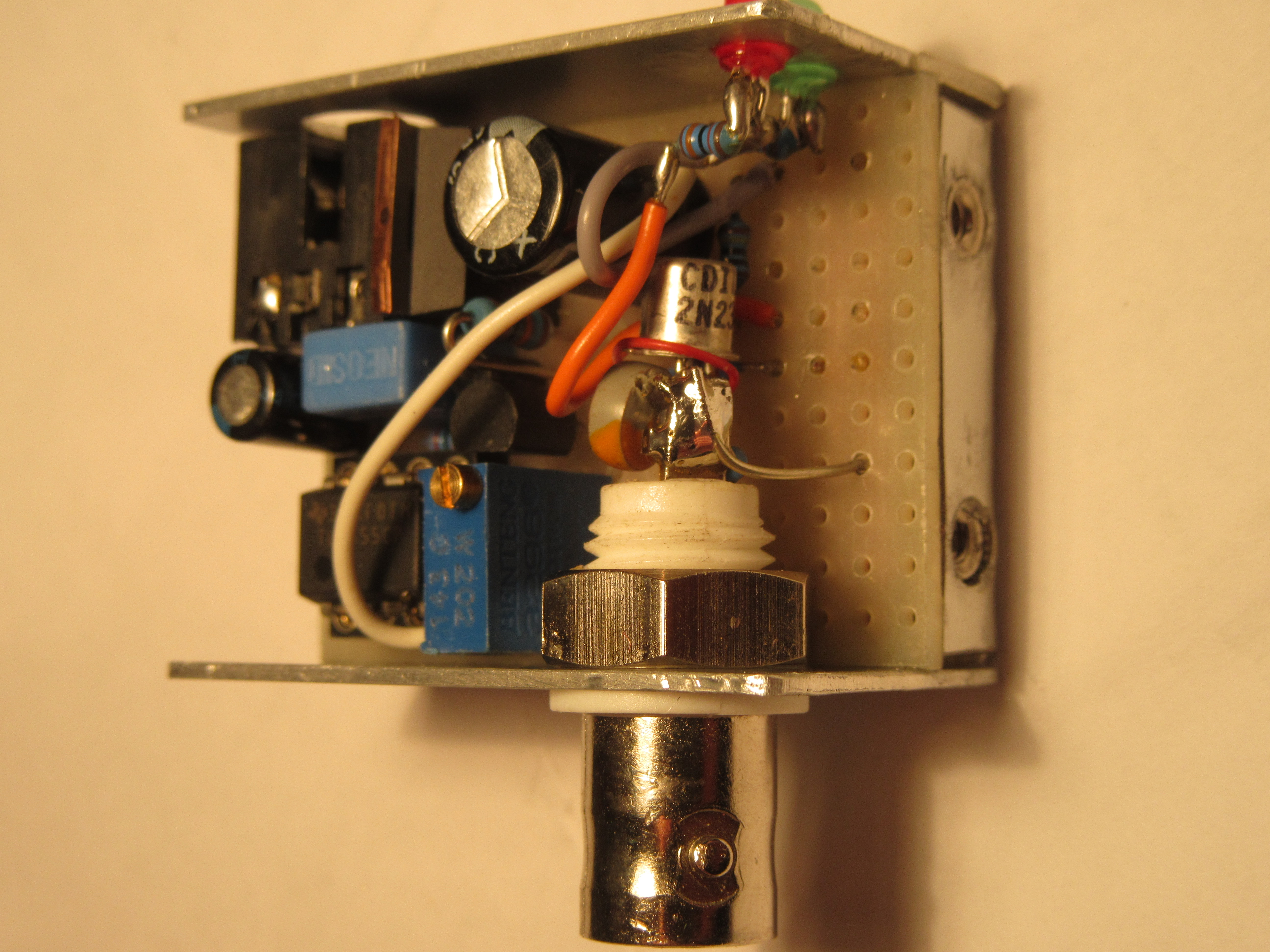
Construction
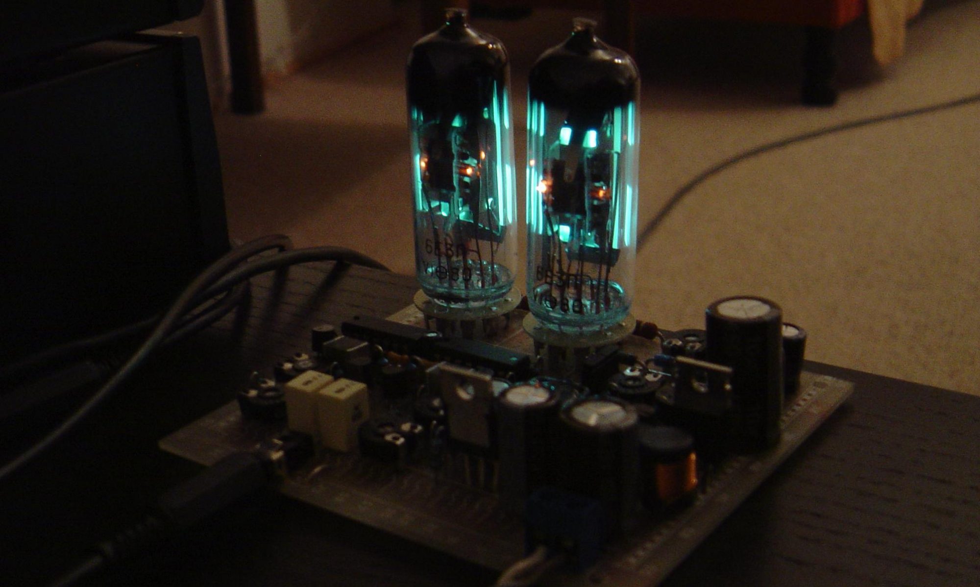
Initially I tried with the 2N3904. My transistor batch purchased from SEGOR-electronics GmbH Berlin had an avalanche breakdown at 130V. At this shop I purchased some 2N2369A too which had the breakdown at about 90V. For this project the 2N2369A is a better choice and I like the vintage TO18 metal case. Depending on manufacturer and production date I suspect a large variance in the avalanche breakdown voltage of different transistor lots. So you have to experiment a bit to find a good matching part.
Shortly the small circuit was assembled and operated at the first go. Excitedly I awaited now the bandwidth check of the oscilloscopes. There is no formula definition to calculate bandwith from rise time. Usually the bandwidth is calculated with 0,35 divided by rise time. The rise time is the time meanwhile the signal grows from 10% to 90% of the maximum.
Oscilloscope tests
First in turn was the good old analog Tektronix 2465B. (1991 model)
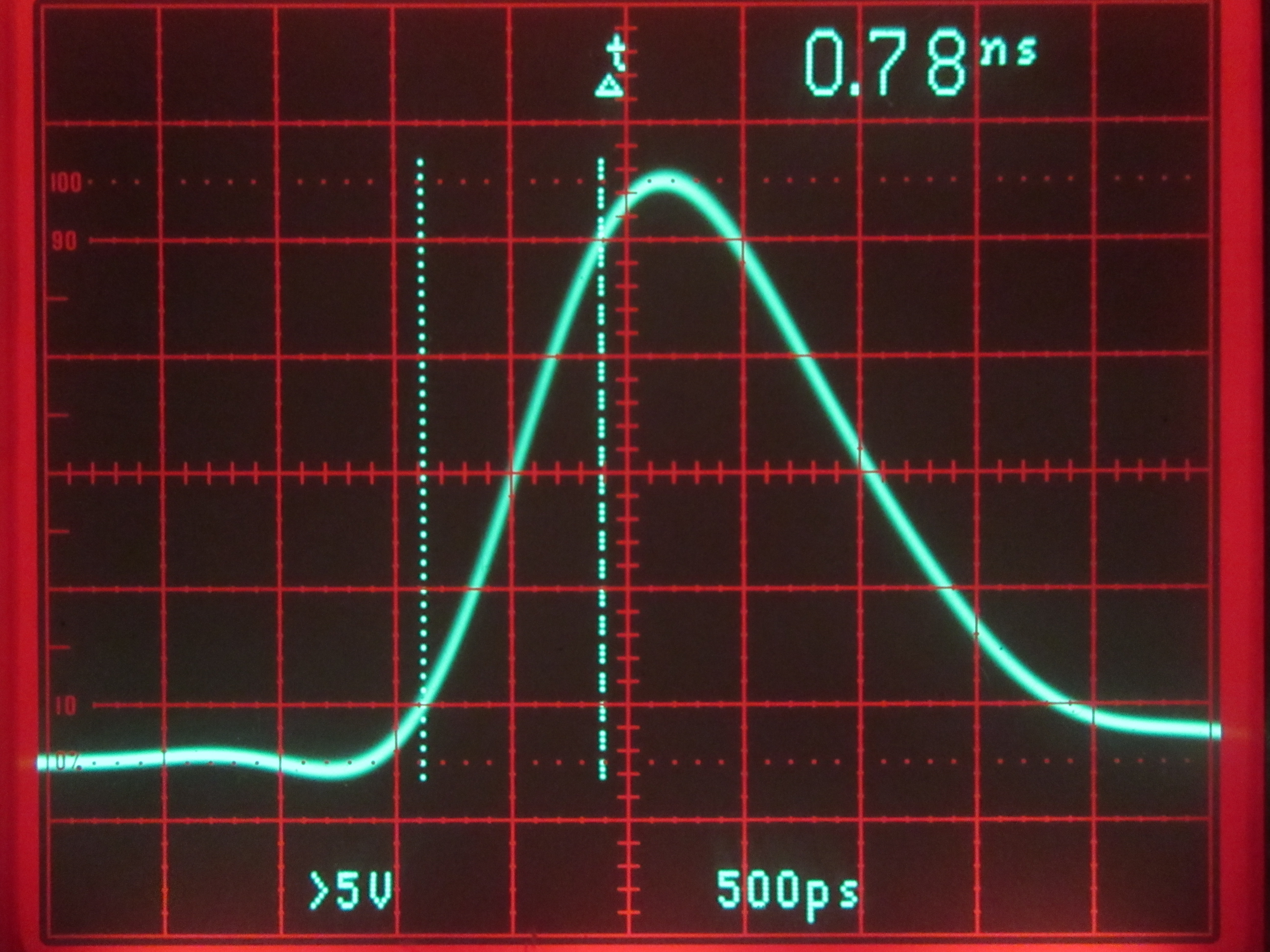
The screen has markers at 10% and 90% and a cursor for Δt which makes it easy to adjust the trace and read out the rise time. The determined 0.78ns rise time is equal to a bandwidth of about 450MHz. This is distinctly more than Tektronix guarantees, I’m satisfied.
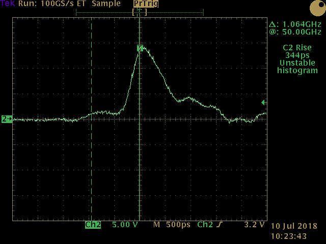
Next in turn was the digital TDS784C. (1996 model)
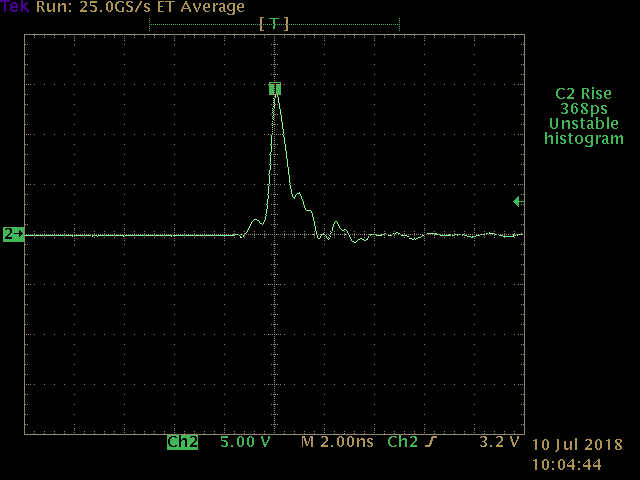
The device can measure the rise time automatically. The result is fairly exact 1GHz bandwidth, as the manufacturer says. Interesting for me was the fact that the signal rise stopped at about 10% for some time and grows very fast later as you can see better with a zoomed x-axis.
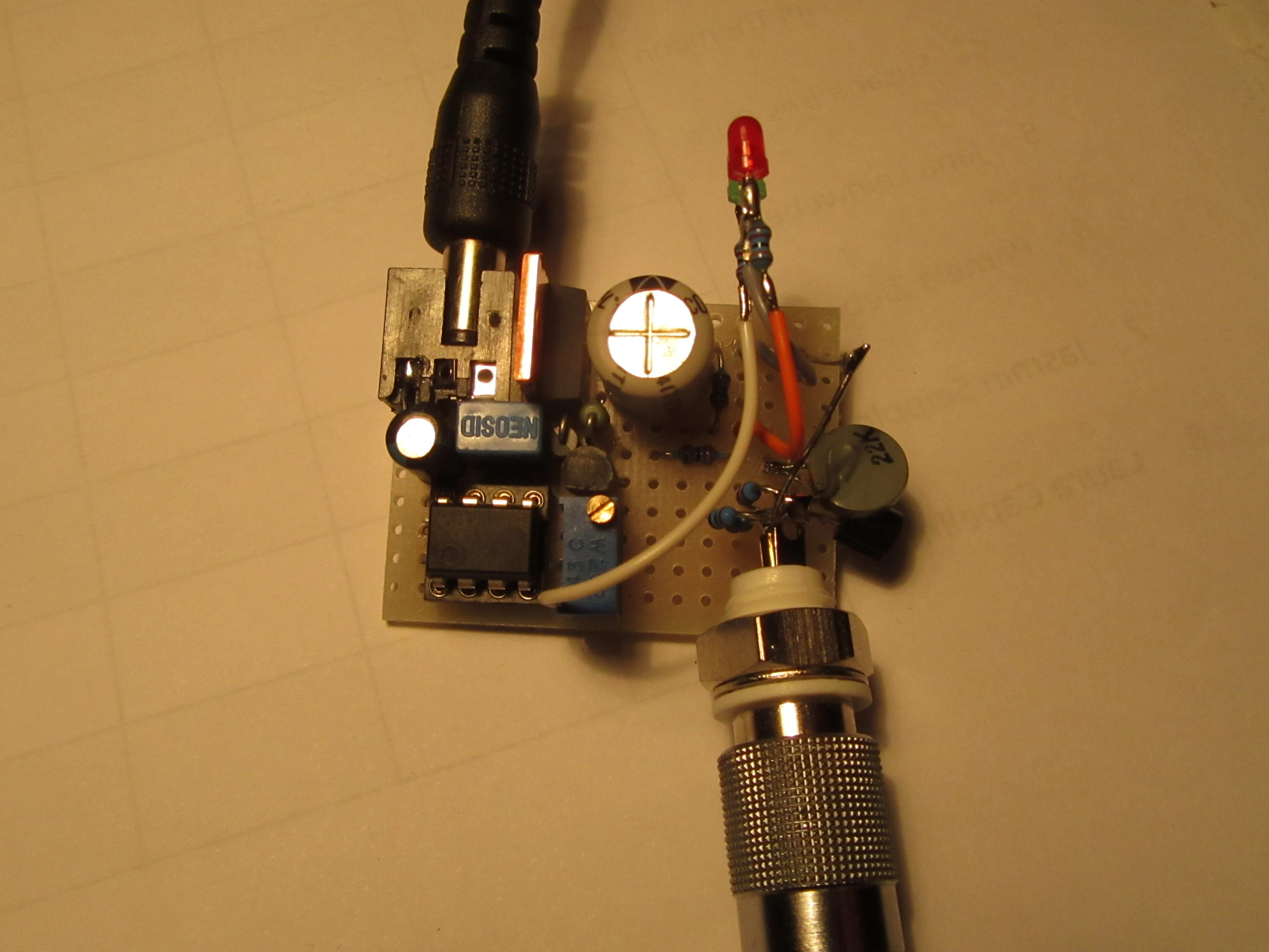
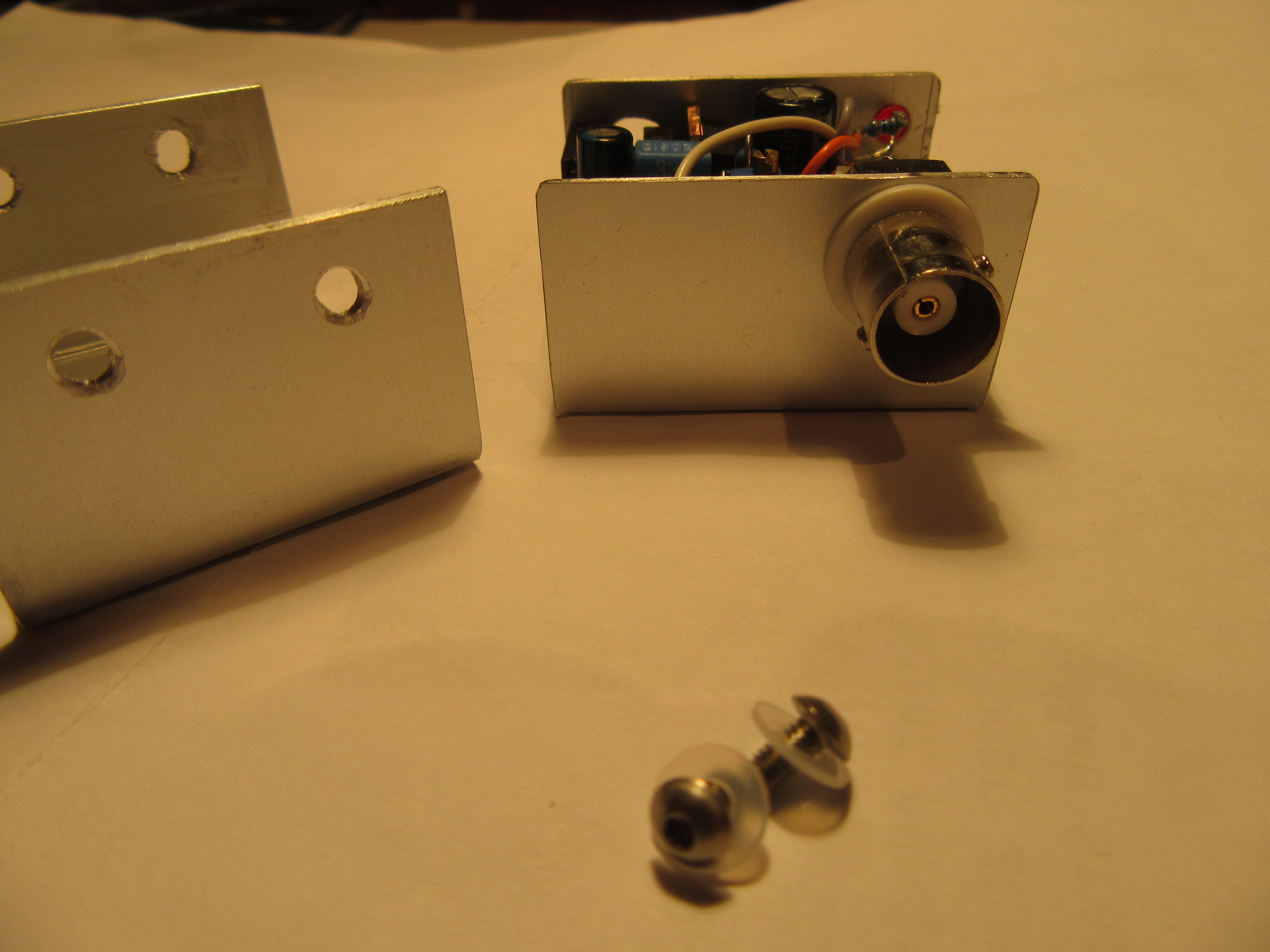
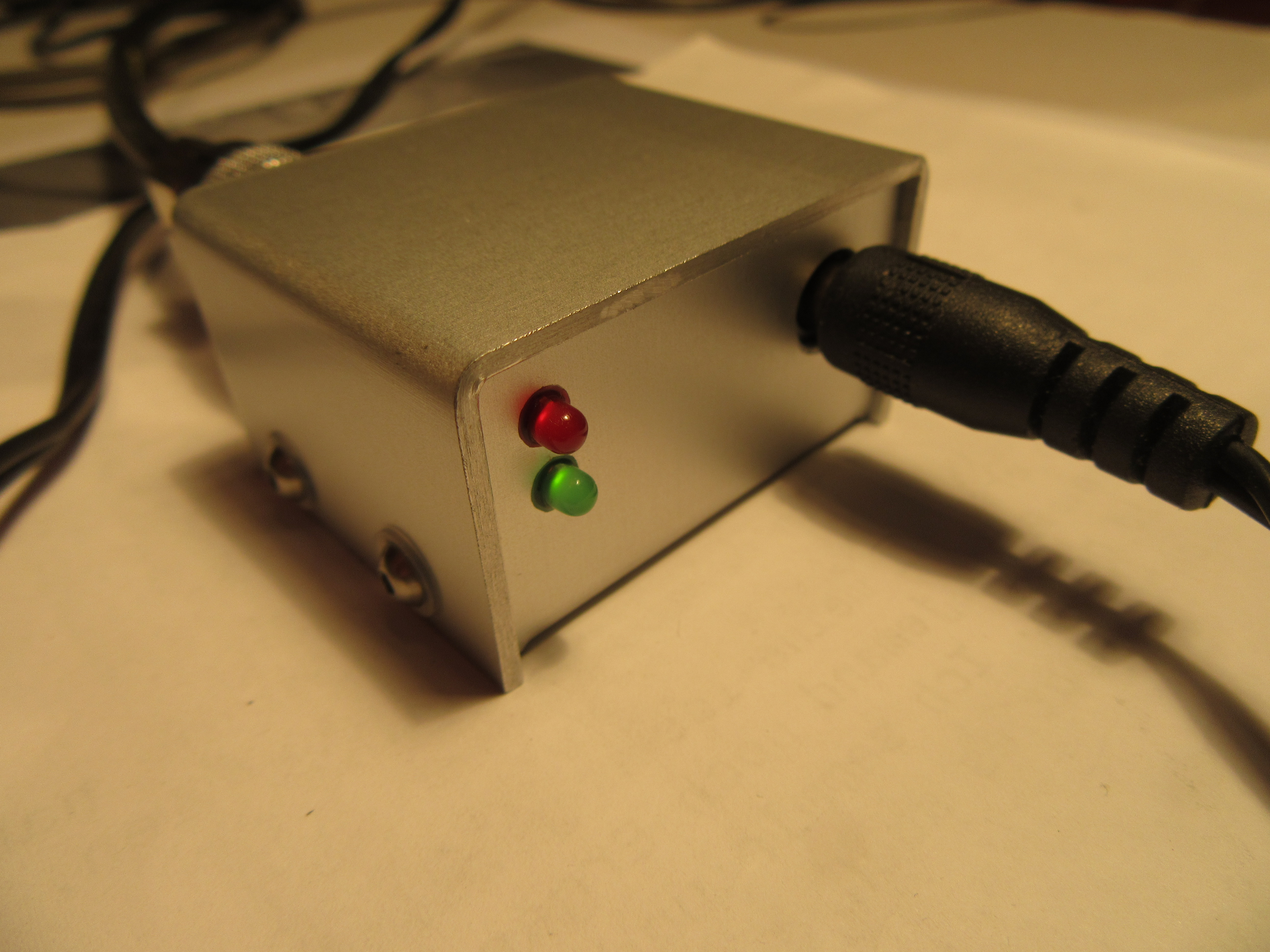
Case
Summa summarum all went as expected and I learned some things. In the end the circuit got a cute case at this time labelled indeed.
Hallo,
auf der Suche nach einem Störgenerator (ich will meine selbstgebauten Schaltungen einmal auf Störsicherheit testen) kam ich als Alternative zum Störgenerator auf den Avalanche-Generator und darüber auf diese Seite. Ich habe mir das Ganze durchgelesen und bin zu dem Entschluss gekommen, dass diese Schaltung genau das ist, was ich gesucht habe. Jetzt habe ich nur 2 Probleme:
1. Könnten Sie mir das Schaltbild als PDF zuschicken? Ich kann die Bauteilwerte nur sehr schlecht lesen.
2. Wie messe ich mit diesem Generator? Ich gehe einmal davon aus, dass ich das Generatorsignal nicht direkt auf meine zu testende Schaltung gebe. Muss ich das Generatorsignal über einen Kondensator einkoppeln, umwickel (wie viele Windungen) ich mit dem Gerneratorsignal meine Messleitung, lege ich das Generatorsignal parallel zu meiner Messleitung?
Ich vergas zu erwähnen, dass ich aktuell eine Füllstandsmessung für meine Zisterne baue.
Mit freundlichen Grüßen
Detlef Gintschel
Hallo Herr Gintschel,
das Schaltbild ist als pdf auf dem Weg.
Punkt zwei ist sehr interessant. So ein steiles Signal hat natürlich jede Menge Oberwellen, die dann Störungen erzeugen können. Auf die Idee, den Generator als Störquelle zu verwenden bin ich noch gar nicht gekommen. Eine genaue Anleitung kann ich deshalb leider nicht geben, nur ein paar Hinweise.
Der Impuls selbst hat eine relativ geringe Energie von ~ 0,12 µJ. Egal wie sie das einkoppeln wird ziemlich sicher nichts zerstört. Jede EMV-Prüfung arbeitet mit Impulsenergien in ganz anderer Größenordnung. Eine kapazitive Kopplung würde ich im Bereich 1 bis 47pF variieren. Ich würde das auf alle Leiter einkoppeln, quasi als Gleichtaktstörung. Den gleichen Effekt hätte das Umwickeln der Leitung. Das ist es aber schwerer zu berechnen, da der Abstand, also die Dicke der Isolation die Kopplung stark beeinflusst und nicht so einfach zu bestimmen ist.
Ich hoffe, dass die Füllstandsmessung für die Zisterne störsicher funktioniert. Wichtig wären symmetrische Signale vom Messpunkt zur Verarbeitungsstelle bei längeren Wegen.
Viele Grüße,
Uwe