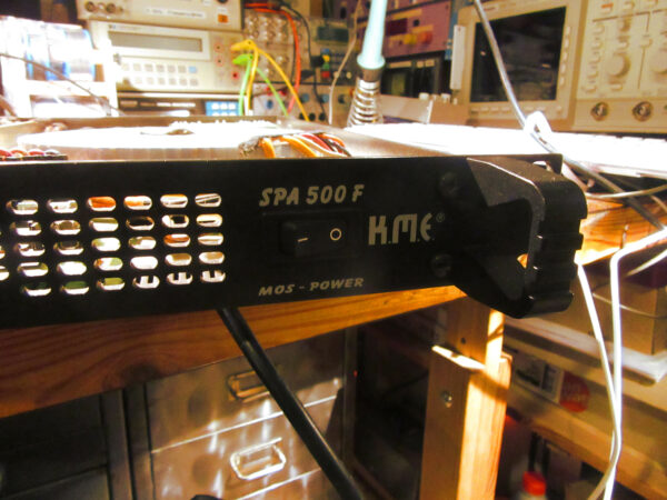
My friend Falk asked me at the beginning of the year if I would take a look at a defective power amplifier that he could buy very cheaply on the Internet. In my opinion, you could not go wrong with it, since the built-in power transformer alone was worth the purchase price. So the power amplifier was ordered and immediately delivered to my home. It was a device from the company K.M.E., model SPA500F with 2x 250W RMS into 4 ohms or 2x 150W RMS into 8 ohms. The year of manufacture was about 2000.The seller described the condition something like this: “One channel does not work, the rest is in top condition, also do not know.” After two days of shipping, the part was with me. The rest of the story I tell as a small picture story below.
Inventory
The first thing to do was the initial inspection, i.e. unscrew the casing cover and take a look.
A strong smell of cold cigarette smoke and burnt electronics and corresponding deposits gave away: The device had been used for years in an environment with a lot of nicotine, probably a discotheque.
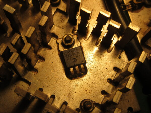
In addition, a lot of components on the board had burned or even exploded.
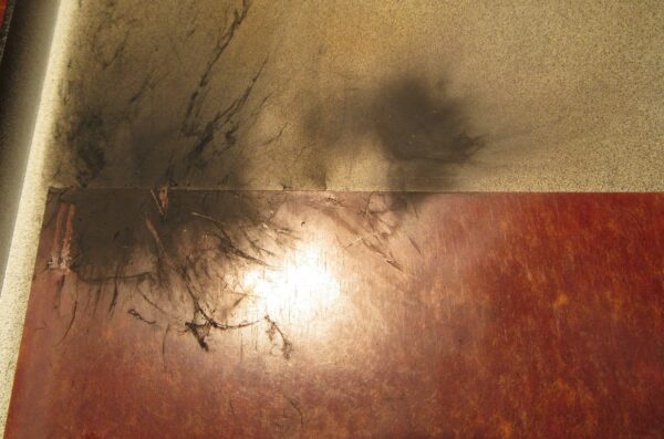
It was also clear that the unit had recently been opened. With the burn marks on the lid and the smell, both of which are hard to miss, the seller may not have been completely honest in his condition description.
Here are some pictures of the exciting parts.
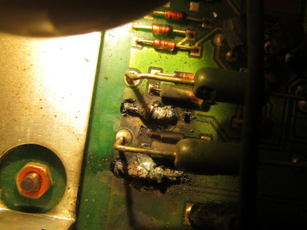
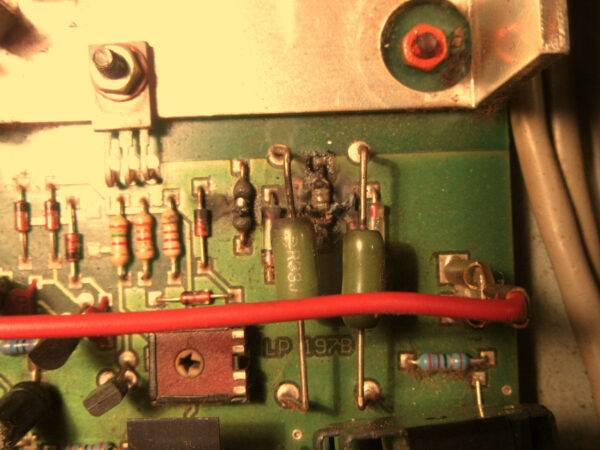
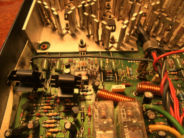
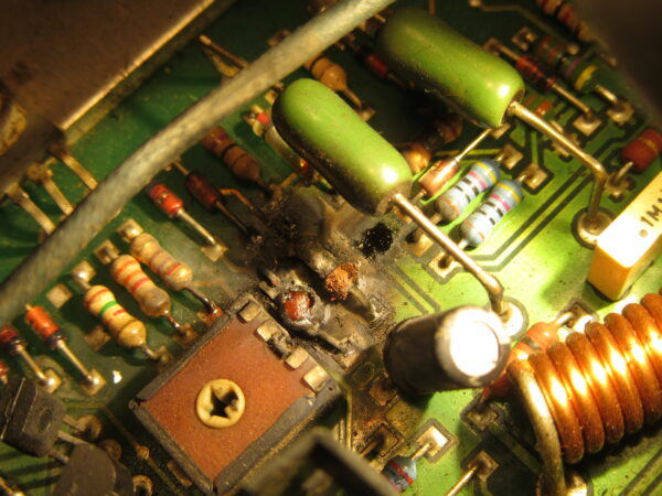
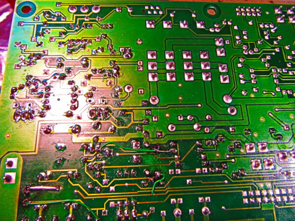
Also some traces had dissolved into nothing. It quickly became clear that I would not get anywhere here without a circuit diagram. A search for the documents on the Internet yielded nothing, so without further ado I sent a friendly request to the service email of K.M.E. over the weekend. And voila, on Monday morning, the schematic and assembly diagram were in my inbox, sent by the production manager himself. Many thanks again at this point.
Defective parts
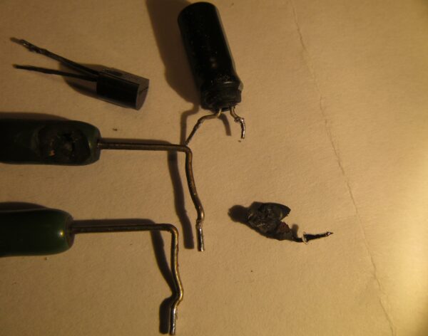
The next step was to find all defective parts and desolder them. As you can see on the photos, a lot of things came together.
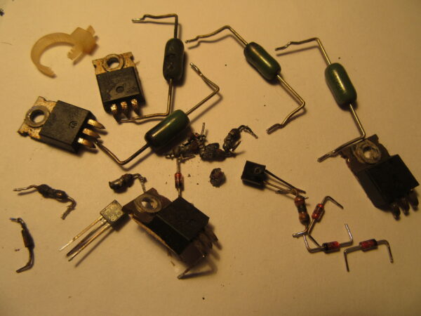
Spare parts
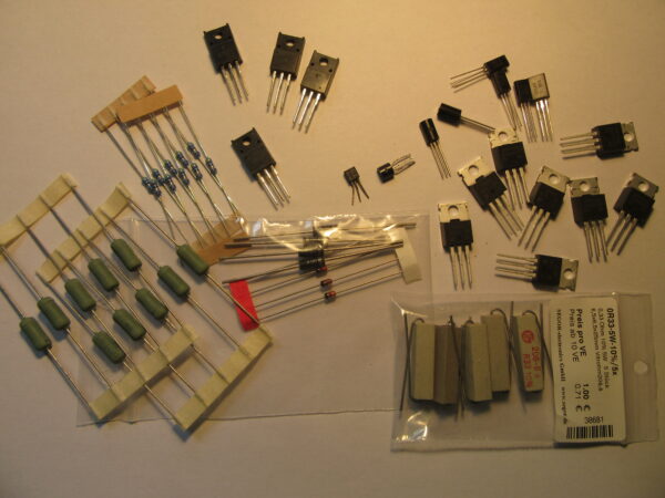
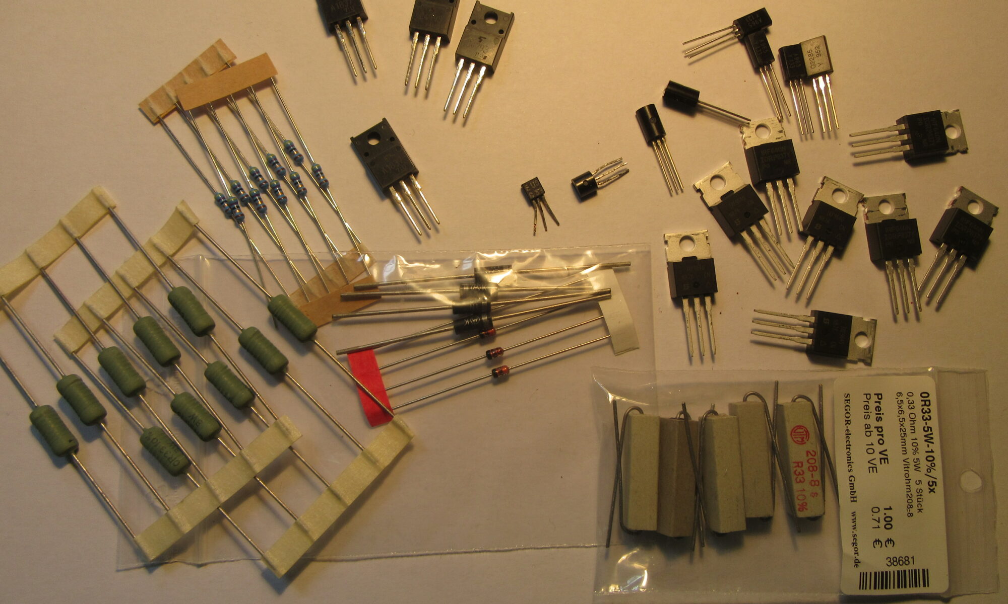
Getting a replacement was easy this time. My local electronics parts dealer SEGOR-electronics GmbH Berlin had everything ready, even relatively exotic Japanese transistors 2SC… were available from stock. However, I had bought the last pieces of a discontinued type.
Replacing the parts was not difficult thanks to the circuit diagram and assembly plan. After a few hours everything was done and the vaporized traces were replaced by thin PTFE-insulated wires.
Test with precautions
Next up was a first test. This is a delicate matter. If you’ve made a mistake or haven’t found the cause, it goes boom, little clouds rise, and you can swap various parts again. A very good insurance against a new disaster is an upstream bulb. This is looped into the power supply so that the maximum power is greatly reduced and in the event of a short circuit, for example, only the bulb lights up and nothing explodes. For a power amplifier of this size a 100W incandescent lamp is appropriate, good who still owns such a thing.
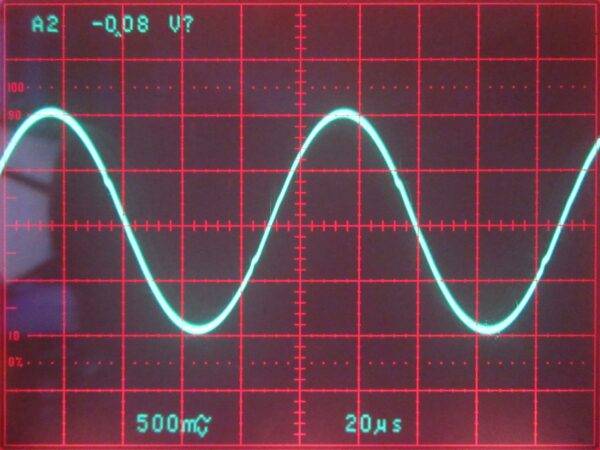
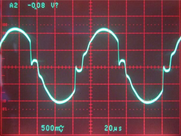
The test went well at first, the fed sinus signal could be seen at the output. However, strong distortions appeared at a slightly higher output level. The unrepaired channel still ran flawlessly.
Tricky troubleshooting
I can briefly summarize the rest of the story. During the repair of the PCB traces I had made a small mistake and connected the drivers of one half-wave with the end transistors of the other half-wave. At low volume the signal was ok, but when the end transistors take over as well, only muck comes out of the speaker. The problem haunted me for a few days. In desperation I changed almost all parts of the defective channel, without success. The unsoldered parts soon resulted in a kind of wimmelpicture.
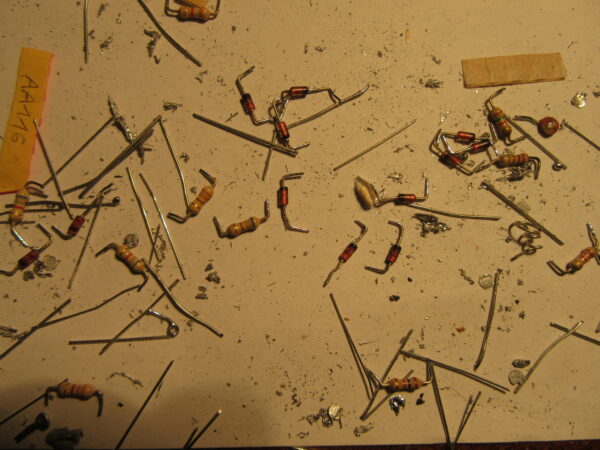
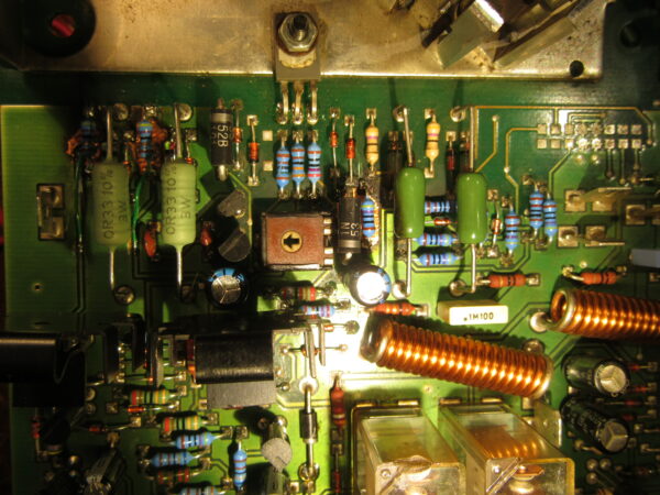
After sleeping on it for a few nights, I systematically searched for the problem again. Great satisfaction when I found the tiny error and fixed it. Actually, I had done everything else right in the first attempt. That doesn’t work out very often with an extensive repair.
Adjustment
The only necessary adjustment is the quiescent current. For this I simply measured the voltage drop across the drain resistors of the intact channel and adjusted the other channel in the same way.
Error cause and update
In the test run, it turned out that the heat sinks get quite hot even without load. The built-in fans are activated at a certain temperature. The idle temperature seemed too high to me. This also matched a change or an update of the device that was in the documents K.M.E. had sent me. The update causes the fans to run permanently at low speed to prevent overheating. So now I think the cause of the defect has been found. It’s pretty sure that one of the end transistors died of heat and dragged several other components with it.
The update consisting of a 220nF capacitor and two 5.6V Z-diodes was quickly installed.
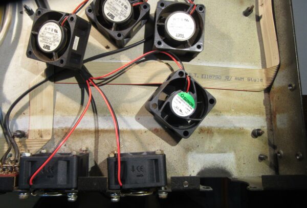
Finally, only the old, out-of-round and quite loud fans were disturbing, which are now permanently on. The quietest suitable model for replacement was quickly found and ordered.
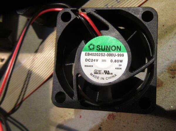
The last official act was the replacement of the three fans.
Sehr schön geschrieben! Viele Grüße
Hallo, sehr gutte Arbeit!
ich habe jetzt gerade auf meinem Tisch gleich so einem KME SPA 500F. Hast du vielleich die Schaltplannem fur mitzuteilen?
Hallo Piotr,
ich habe Dir eine Nachricht gesendet.
Viel Glück beim Reparieren!
Uwe