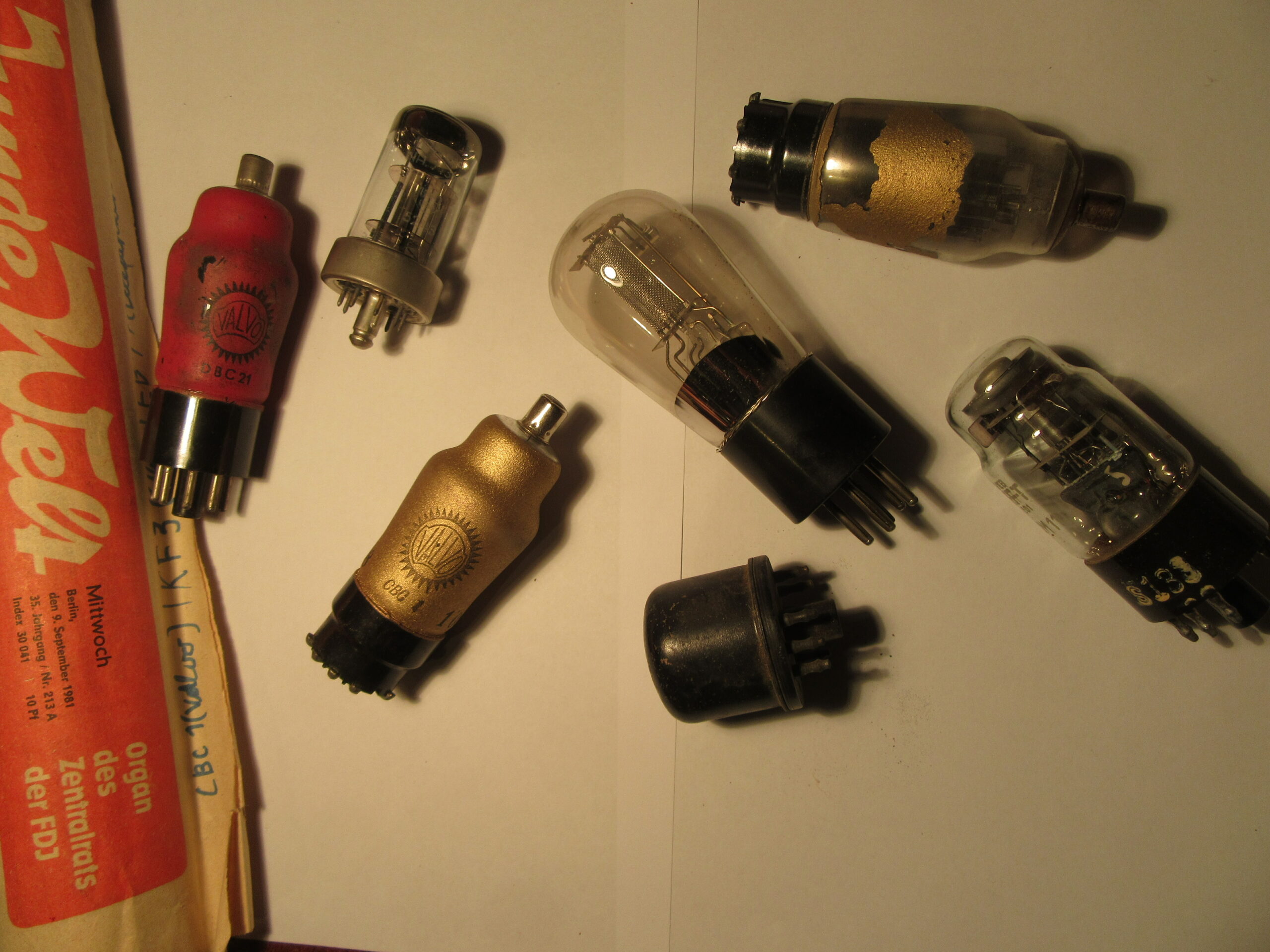
Already as a small boy I collected tubes and other useful things in the bulky waste. A few pieces that were already old at that time went into an old cardboard box that I had opened again sometime in 2007 or so.
I was fascinated by the idea of bringing back to life components that had been dormant for at least 50 years. It took me about a year to put this idea into practice, since I first had to procure the necessary equipment or build it myself. At the end there was a very nice high voltage power supply for tube experiments, some restored tube radios, a lot of learned stuff and of course some tested specimens from my mini collection.
So below are all the articles where tubes are an important topic. Mostly about restoration of old devices but also about new construction and tests.
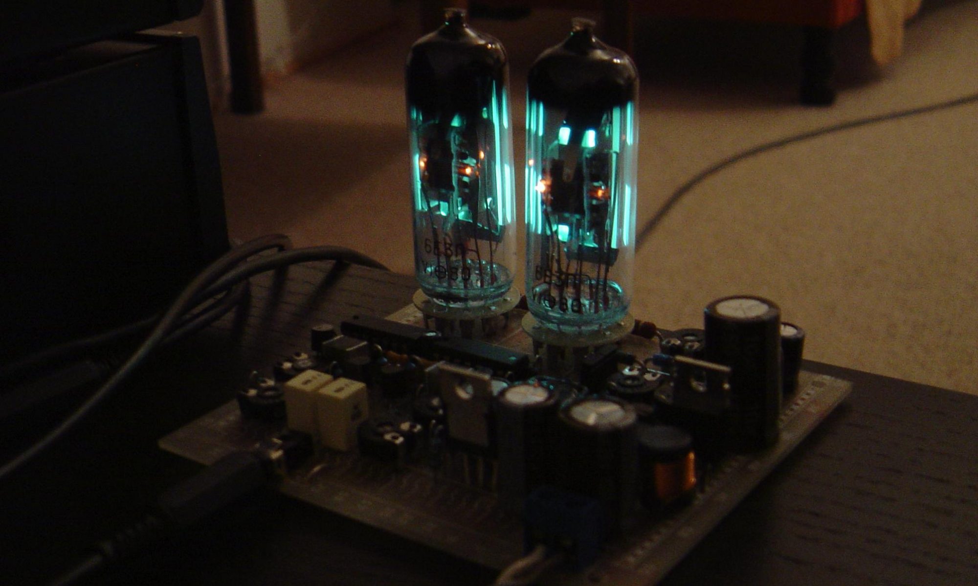
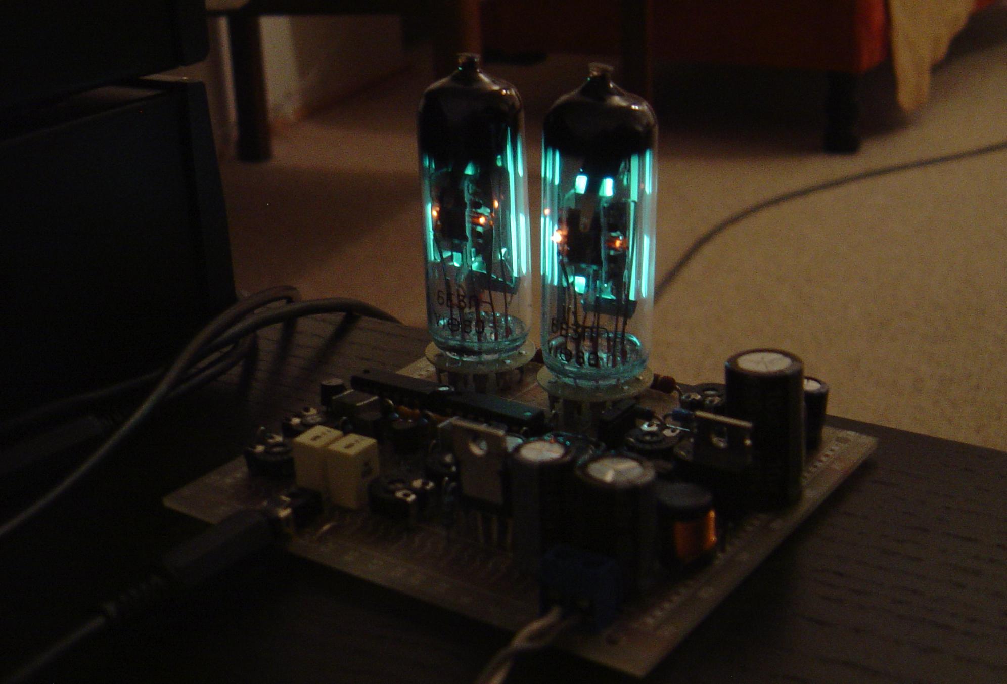
This is a retro project I built in 2014. I was looking for a nice VU-Meter with tubes but didn’t find any project in the internet that fulfilled my requirements. So I had to develop a circuit by myself with the “magic bar” tube EM84. The front page picture of this blog shows the finished project in operation.
tubes with glowing heaters
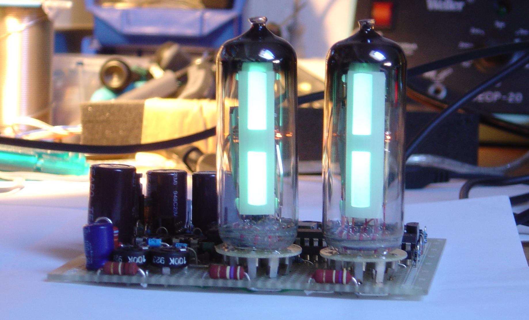
For the tubes I used a cheaper and NOS replacement from Russia, 6Е3П. The control electronics, made with four operational amplifiers of a TL064, does the signal amplification, logarithmic function, peak detection and an analog adder to adjust the zero point. An N-FET current source is used to realize the linear drop. For better thermal stability of the calibrated circuit the TL064 can be replaced by a LT1014 precision Op Amp.
There are two switching regulators to create all needed voltages from a single 12V supply. The first regulator with a TLC555 as controller creates the anode voltage of approximately 240V. From that source four other voltage potentials for the operational amplifiers are derived with a chain of Zener diodes. The second switching regulator is a modern one, LM2575T-ADJ. It is used to efficiently create the heater voltage of 6.3V.
The sum of all features makes this project unique and most professional compared to a lot of similar circuitry found in the internet.
project goals:
single power supply of 12V
logarithmic scale
constant current source for linear drop
multiple adjustment possibilities to match unequal tubes
aesthetic scene
prototype front viewprototype top viewprototype side view
First, I have to give a quick heads up: this post is a little longer than usual but that’s how it is with a hobby. You have a plan, you learn new things in the middle of it, and you expand a project piece by piece. A hobby is not about efficiency, but about making something “beautiful” and being satisfied at the end. So it doesn’t take long to add a few extra weekends of tinkering to something that should only take a few hours…
From the planned test of the O7S1 had resulted in the course of the time also these points:
Sawtooth generator, test setup and simulation with PSpice
Amplifier for X- and Y-deflection with double triode 6N2P
Overall circuit for a mini oscilloscope
But now let’s get started with the article.
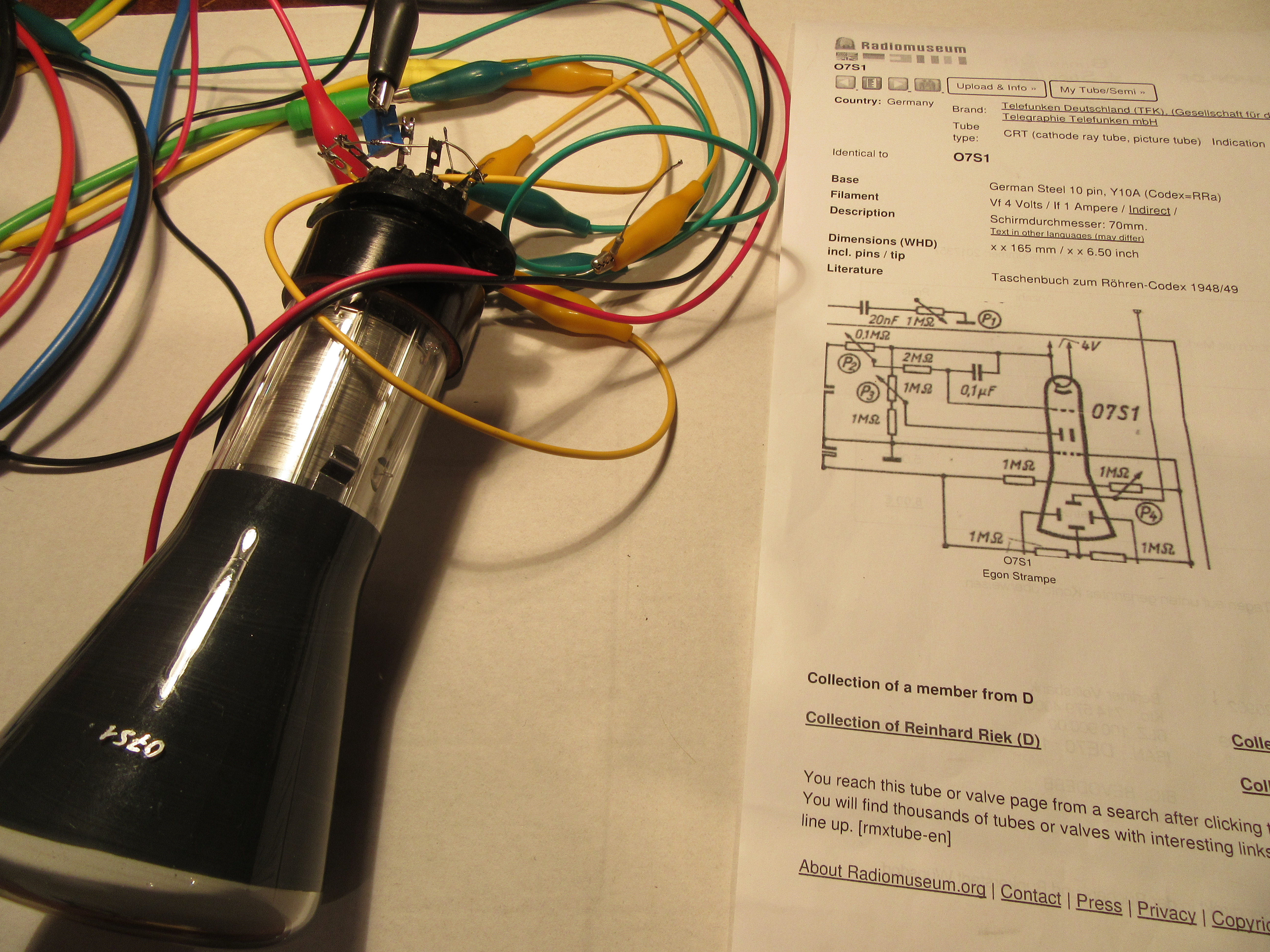
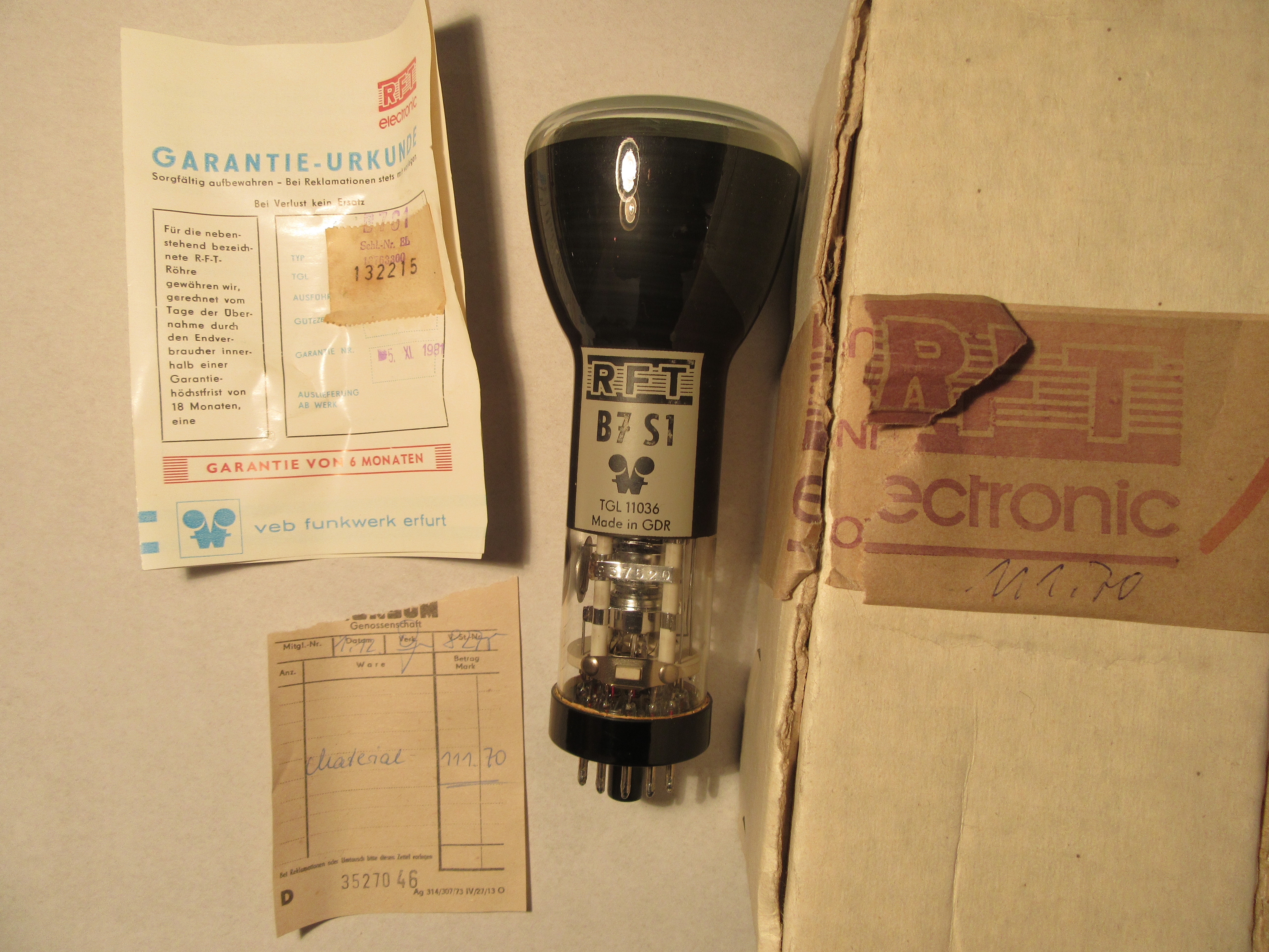
Recently I rebuilt an old oscilloscope “Picoscope”. Among some other things the cathode ray tube was missing. In the original device a B7S1 from VEB Funkwerk Erfurt (part of RFT) is installed. The designators of such tubes are usually composed like in this case: A letter followed by the screen diagonal and the more exact designation. In this case, B7S1 probably stands for picture tube, 7cm diagonal, system 1. After a short internet search for this spare part, I didn’t find a B7S1, but an O7S1 for a relatively low price. A further search in my tube codex from 1948
“Röhren-Codex” 1948
and at radiomuseum.org revealed that an O7S1 is a pre-1945 Telefunken picture tube model. It has the same heater voltage and apparently the same socket circuitry as a B7S1. Further data on the O7S1 was not available. Unfortunately, my “Röhren-Taschenbuch” from 1958 from the “Fachbuchverlag Leipzig” does not contain the B7S1 yet.
“Röhren-Taschenbuch” Volume II, 1958
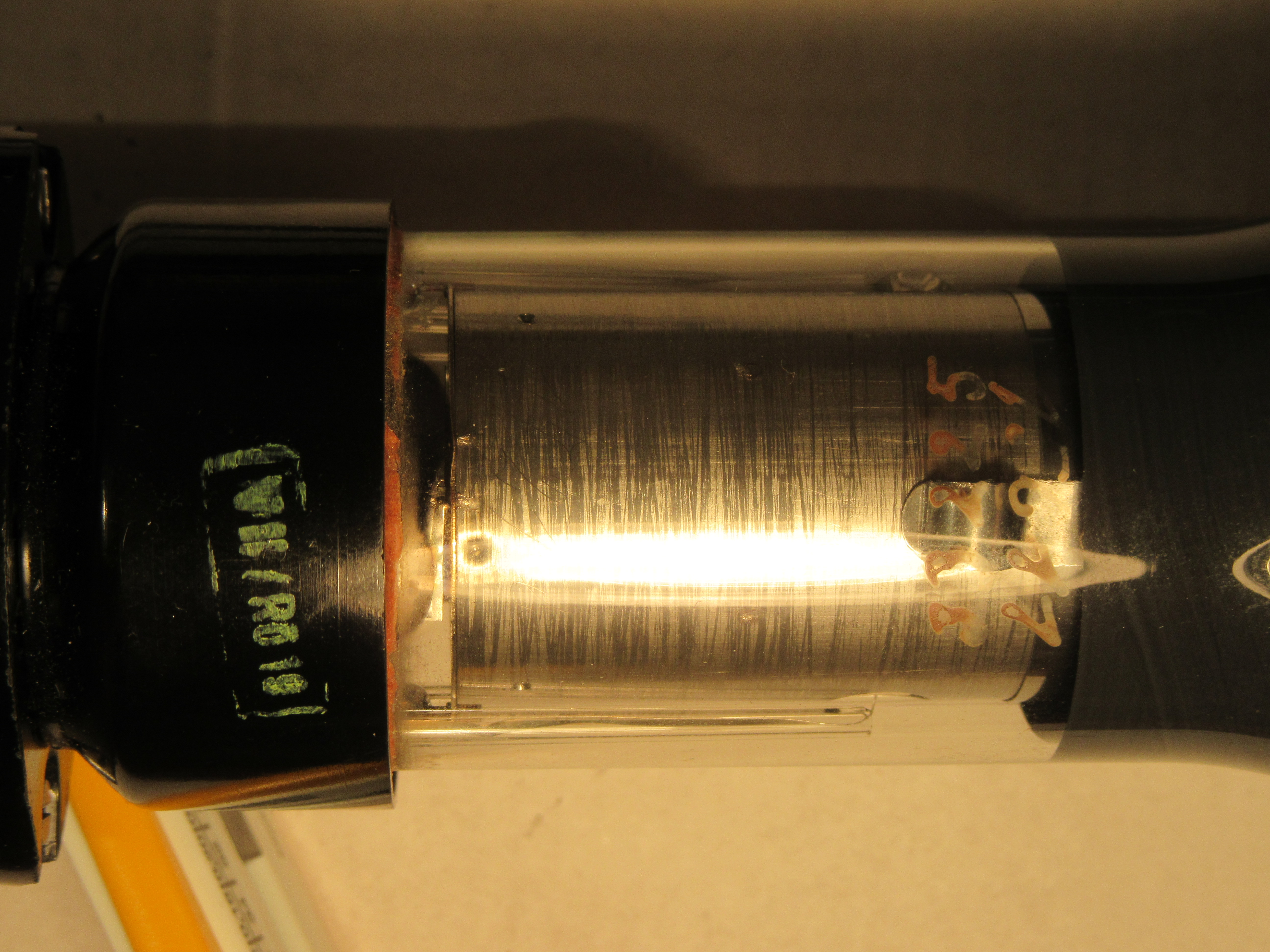
However, the similarity between the two tubes led me to believe that the B7S1 from RFT from the 50s is a compatible replica of the Telefunken tube from the 40s. So I bought it without further ado and after a few days the tube arrived undamaged. The first sight was good. Externally and mechanically everything was apparently in order, the contacts had not been in a socket for ages. This can be seen quite easily with a magnifying glass on corroded but not scratched contacts. Also the Telefunken logo and the designation are still held diagonally against the light, quite good to see. The silver inscription O7S1 is applied from modern times with one of these special pens.
O7S1 designation and Telefunken logo
On the base itself was the original imprint V II / RÖ 19. It occurred to me briefly whether it might not be Roman seven, but V Roman two or V2. Probably, however, it means assembly 7 / tube 19. If anyone knows which device it could be, I absolutely ask for a message.
O7S1 socket detail
Since I still have an original Picoscope EO1/7, I could put the tube in there and do a quick test. But everything remained dark. Nevertheless, I did not give the online dealer a bad rating at first, but set up a test circuit. Very helpful was the page of Burkhard Kainka, on which beside many basics as well as small and large tinkering projects also a test circuit for a mini-oscilloscope is published. At this point a big thank you from me to the operator of the site for the work to publish all this.
Back to the test circuit: During the setup it quickly became clear that the sockets of the two tubes B7S1 and O7S1 are rotated by 180° and after a short time I could see that the tube basically works.
O7S1 First test
What followed was a few weekends of tinkering. First I found out that grid 1 has no function anymore. This means that direct brightness control is no longer possible. This is not so much a problem, because you can also regulate the brightness with the anode voltage. However, it may also affect the focus, and probably the tube will no longer have the performance it had in its original state. Nevertheless I tried to develop the best possible circuit. Basis was as described above the test circuit of Burkhard Kainka.
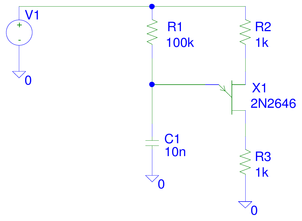
First I tried to improve the X-deflection. Ideal is a sawtooth generator, which has a linear voltage rise and very fast fall. However, the original flip-flop circuit with a glow lamp gives an exponential voltage waveform. You can see this very clearly in the oscillogram in the article by Burkhard Kainka, the curve is compressed on the right. My idea should be as simple but a bit better and finally I experimented with a sawtooth generator with a unijunction transistor (UJT), whose basic circuit is quite simple.
Schematic PSpice simulation sawtooth generator with UJT 2N2646 first try
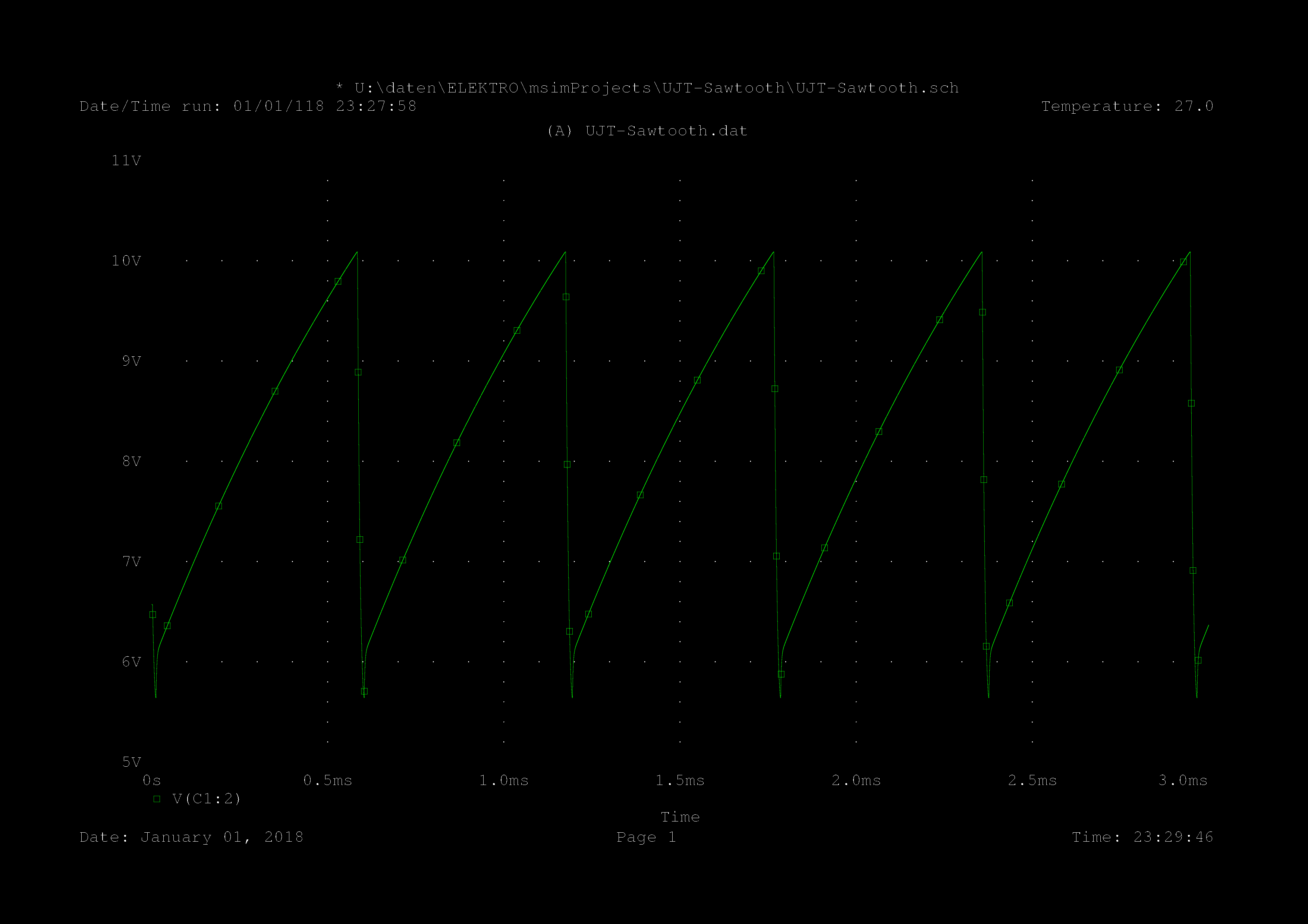
At the emitter a sawtooth can be taken, which is already a bit more linear than a toggle circuit with glow lamps. Of course it is again the charge curve of a capacitor or an e-function. But here we are only in the lower range. A simulation with PSpice shows the expected, a not quite linear increase.
PSpice simulation sawtooth generator with UJT 2N2646, first try
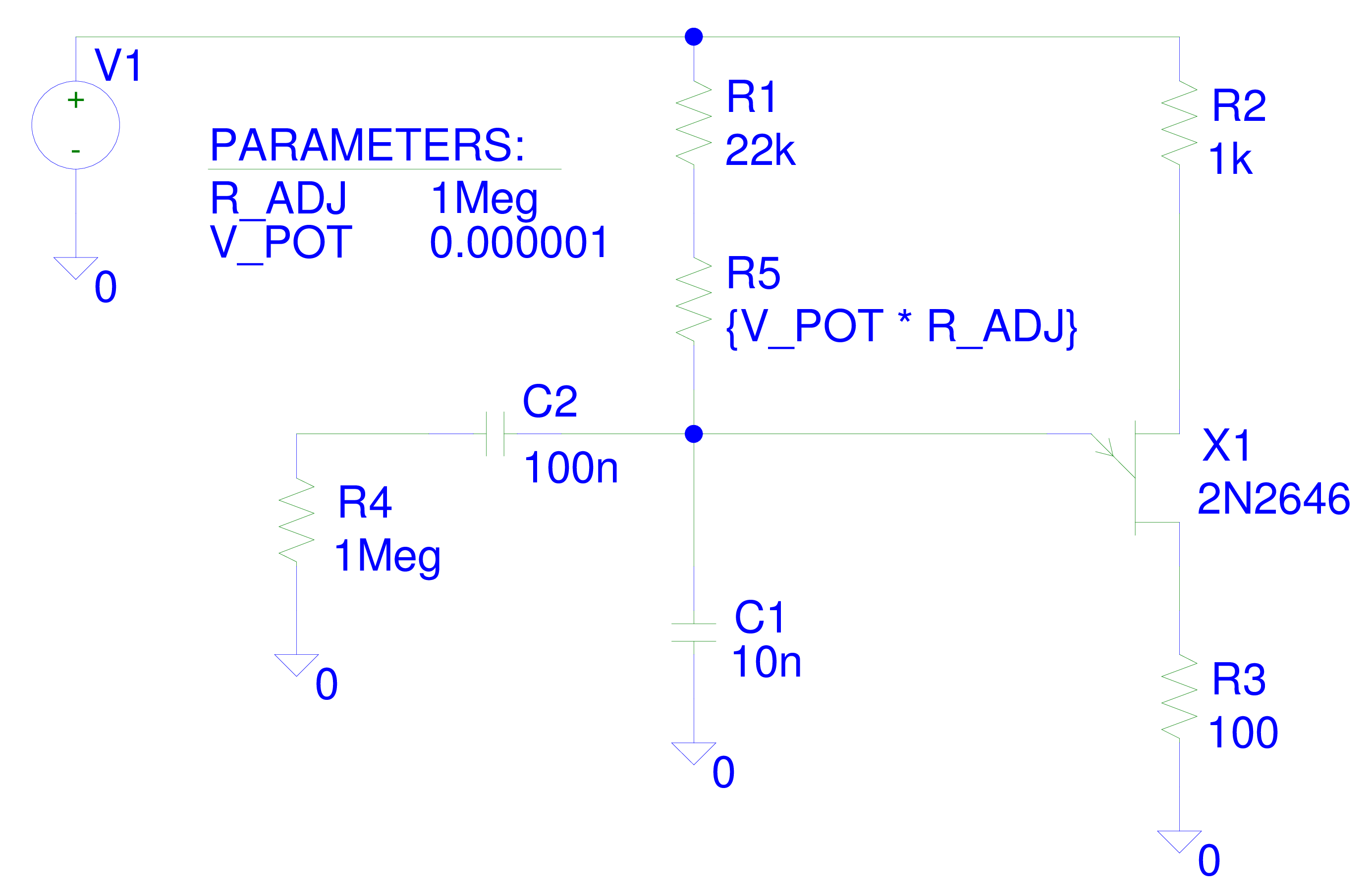
Since the frequency should be variable, I have inserted a resistor into the circuit, which is changed during the simulation via a parameter. With PSpice this is done by placing a global parameter on the worksheet, in this case V_POT. Several simulations are then run and this parameter is changed. I have chosen steps of 0.2 between zero and one. Via C2 and R4 the load of the generator is represented.
Schematic PSpice Simulation Sawtooth Generator with UJT 2N2646
Again, the simulation did not reveal any surprises. However, it was quite difficult to get the convergence problems under control with PSpice. This is especially problematic when simulating oscillators and one has to experiment with some simulation parameters until everything runs error-free to the end.
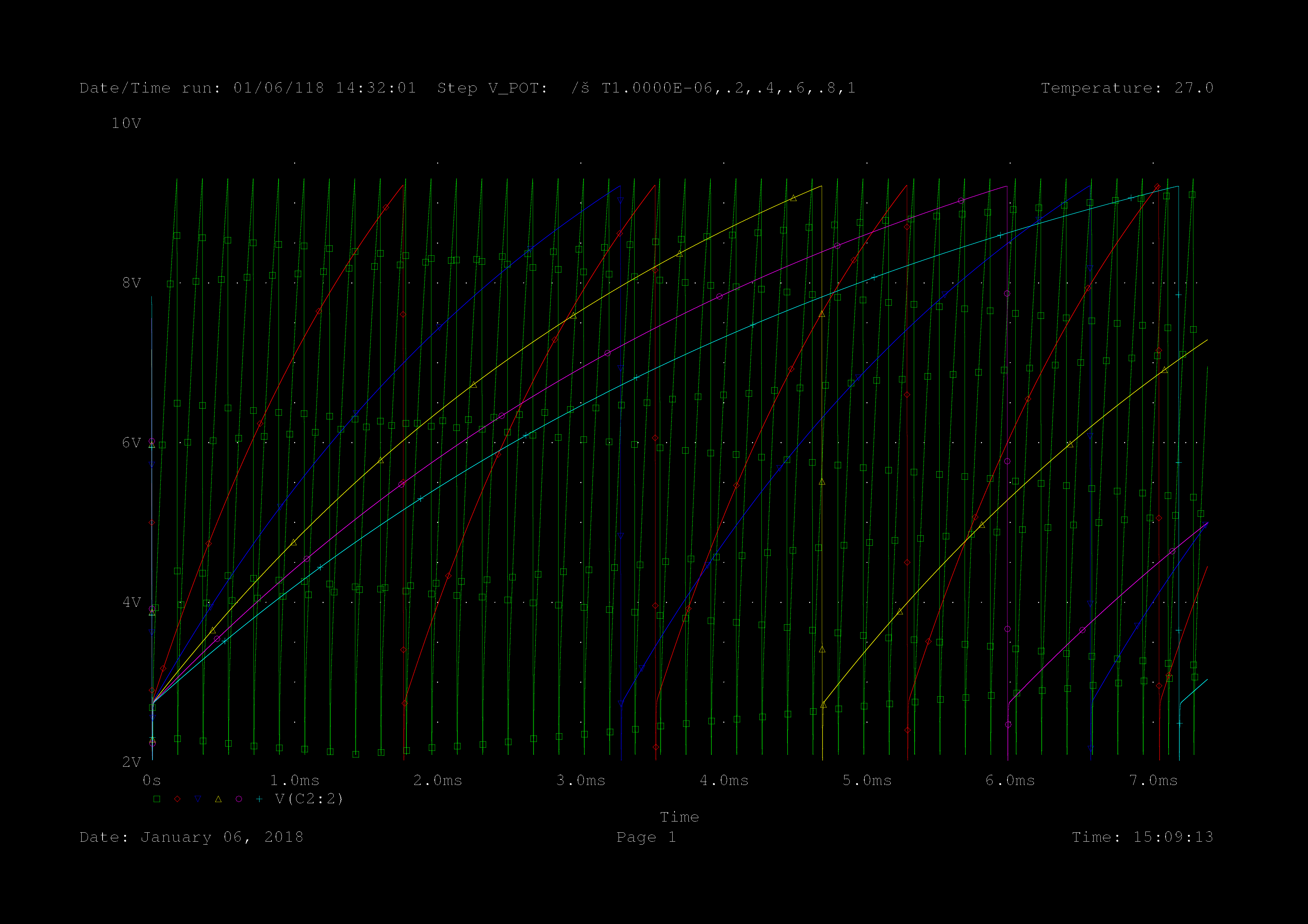
The frequency is adjustable within wide limits, we now have an excellent sawtooth generator for the X-deflection.
PSpice simulation sawtooth generator with UJT 2N2646, 7.5ms
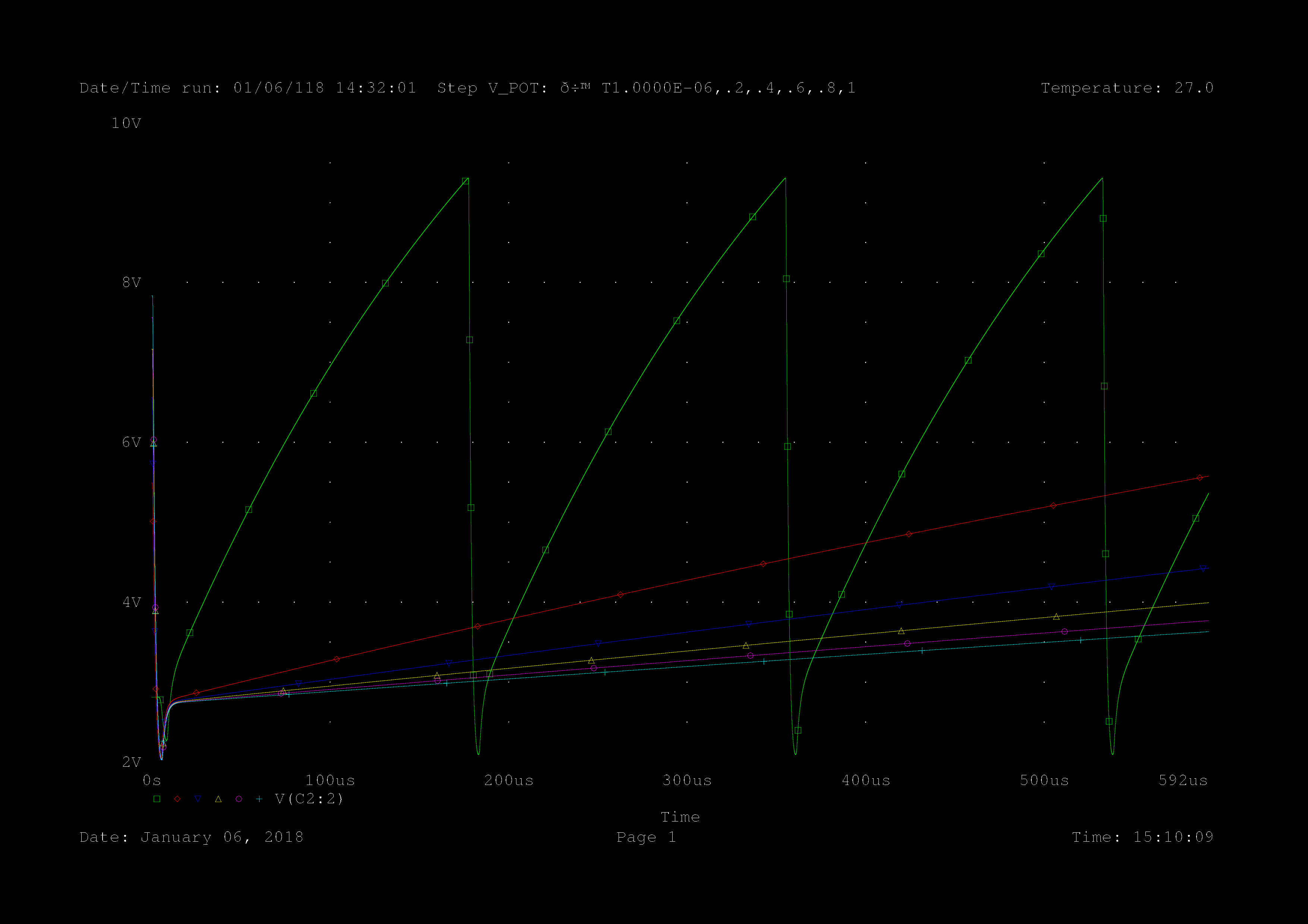
And another clip of the first half millisecond.
PSpice simulation sawtooth generator with UJT 2N2646, 500µs
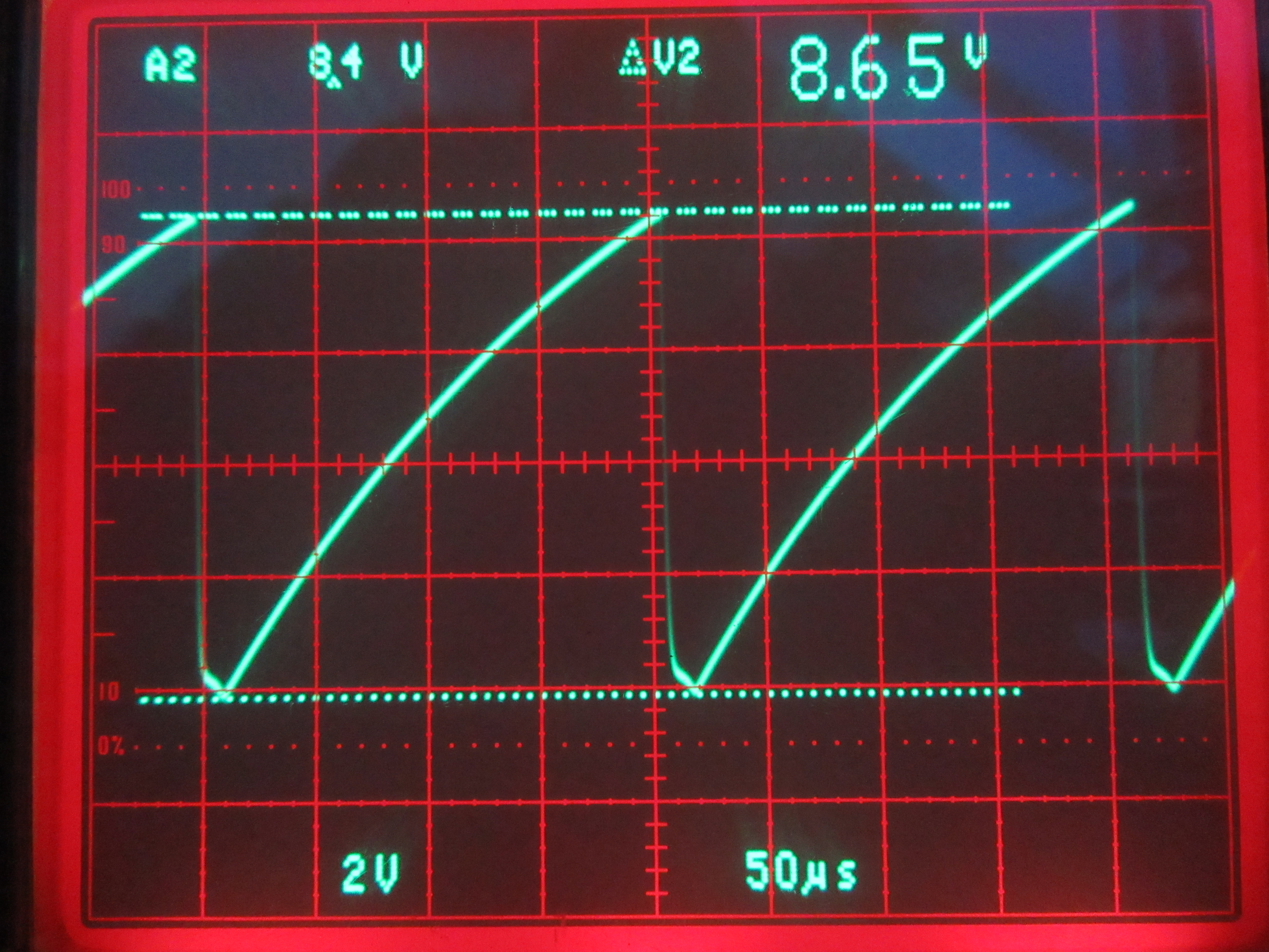
At the end I made an oscillogram of the built up sawtooth generator at minimum frequency, so it should look like the green curve. And voila it looks pretty similar. The amplitude is a bit higher and the frequency is a bit lower. I blame this on the component tolerances.
Oscillogram sawtooth generator with UJT 2N2646
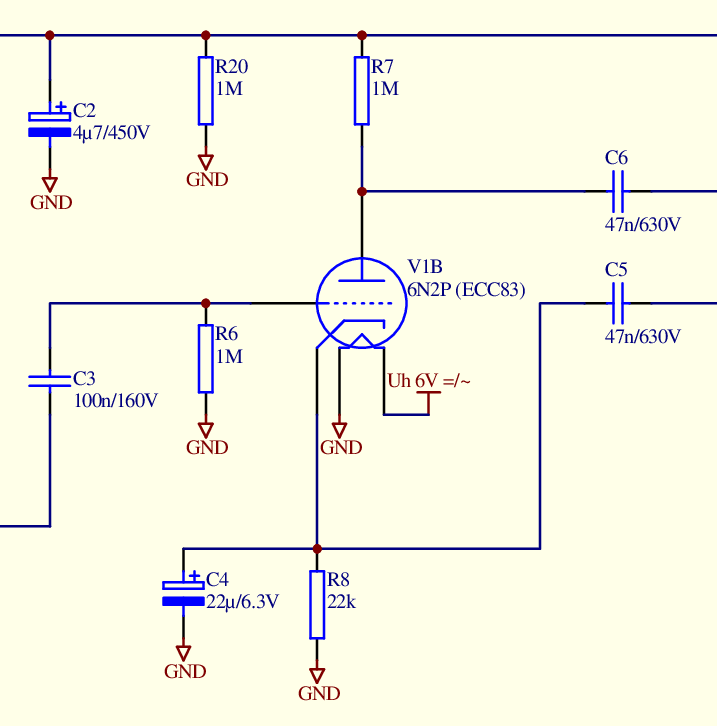
The sensitivity of the O7S1 is rather moderate. The exact value is not known to me. My tests showed about 50V/cm for the X- and 40V/cm for the Y-deflection. This left the next task to be solved, to amplify the signal by a factor of 25 to 30. True to style I chose a triode. The high voltage for the picture tube is available anyway, so the use of another tube does not mean a big additional effort. As a triode with high amplification an ECC83 is a good choice. Because of the high price of the ECC83 I chose the very similar 6N2P or 6H2П, which is still manufactured in Russia. As circuit a standard amplifier circuit for triodes is used. Here is the section of the overall circuit diagram of the mini-oscilloscope.
Circuit diagram amplifier with triode
The second system of the double triode was used for the Y-amplifier, which is constructed identically to the X-amplifier. Some of the deflection plates must have a higher potential than the anode to be able to shift the X and Y origin over the whole visible range. This function is realized by some voltage dividers and potentiometers (R9 to R19 and P2/P3). With potentiometer P4 the focus is set. With this the mini-oscilloscope worked reasonably well and I was satisfied.
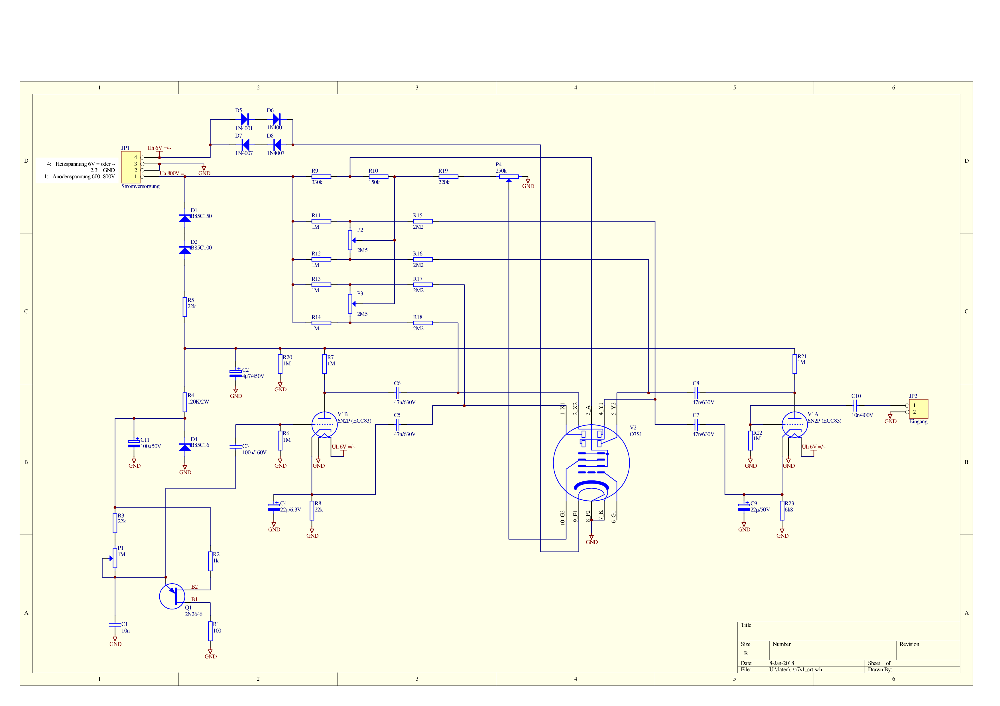
Finally the complete schematic, a photo gallery and a short video.
Complete schematic
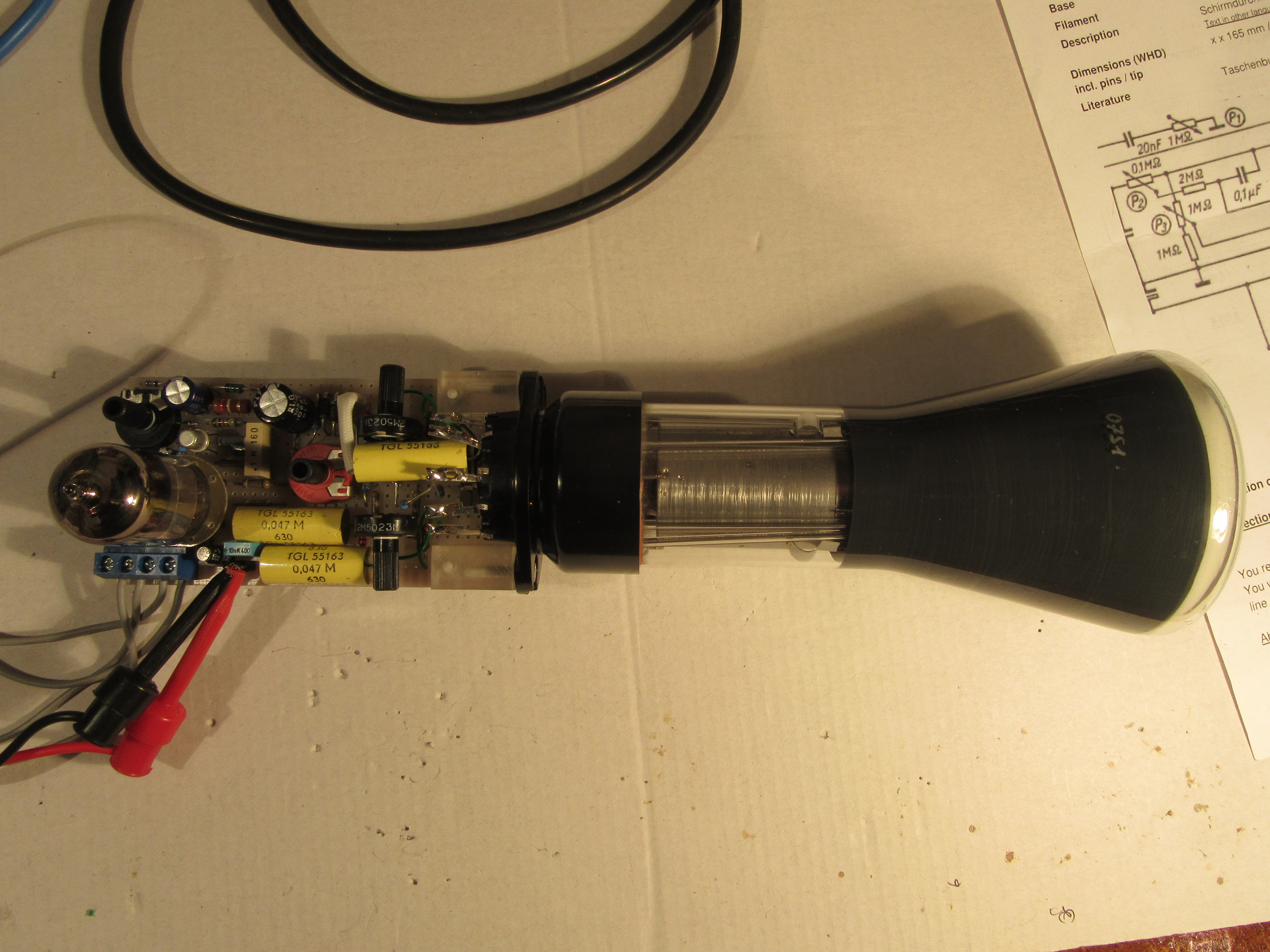
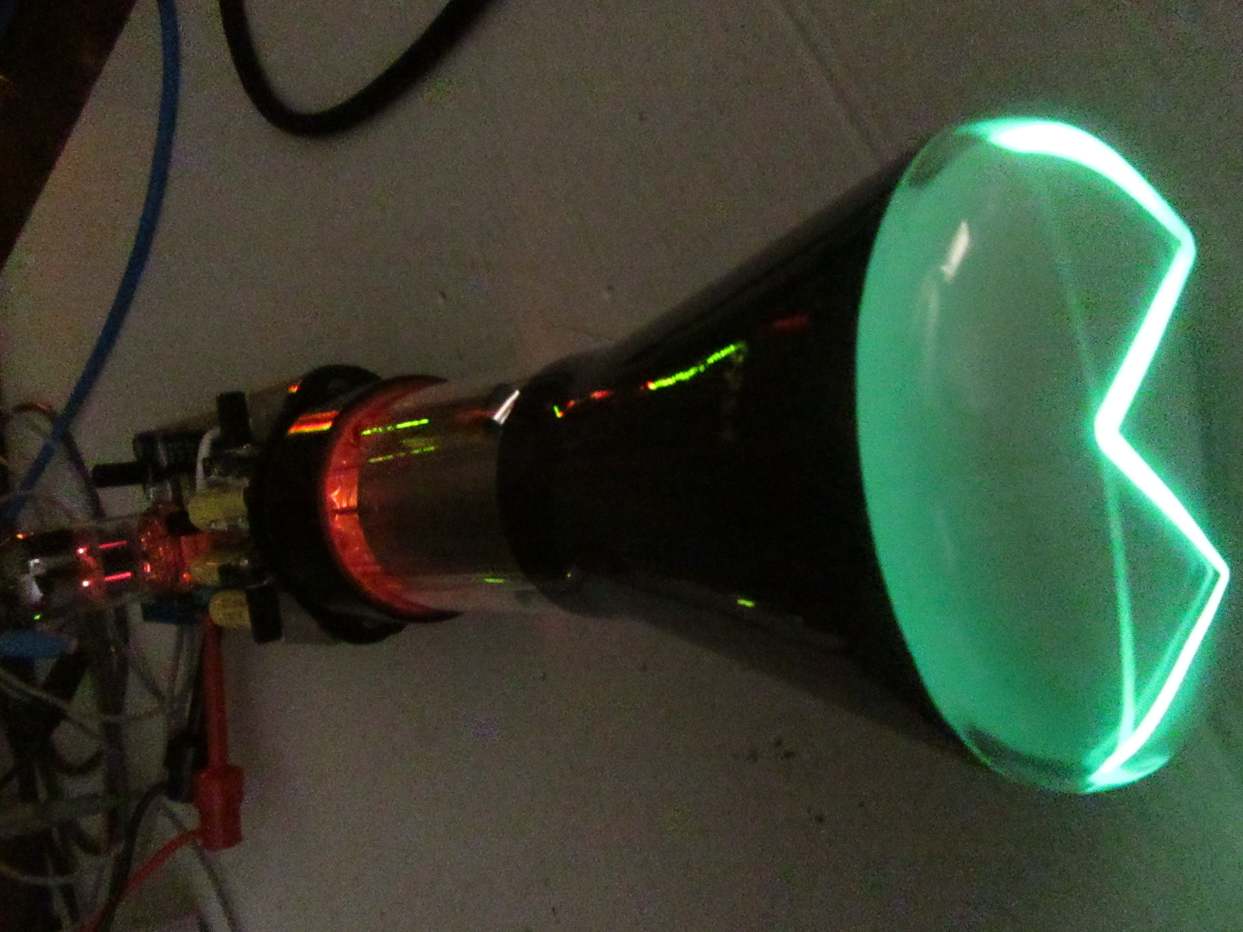
Mini oscilloscope complete
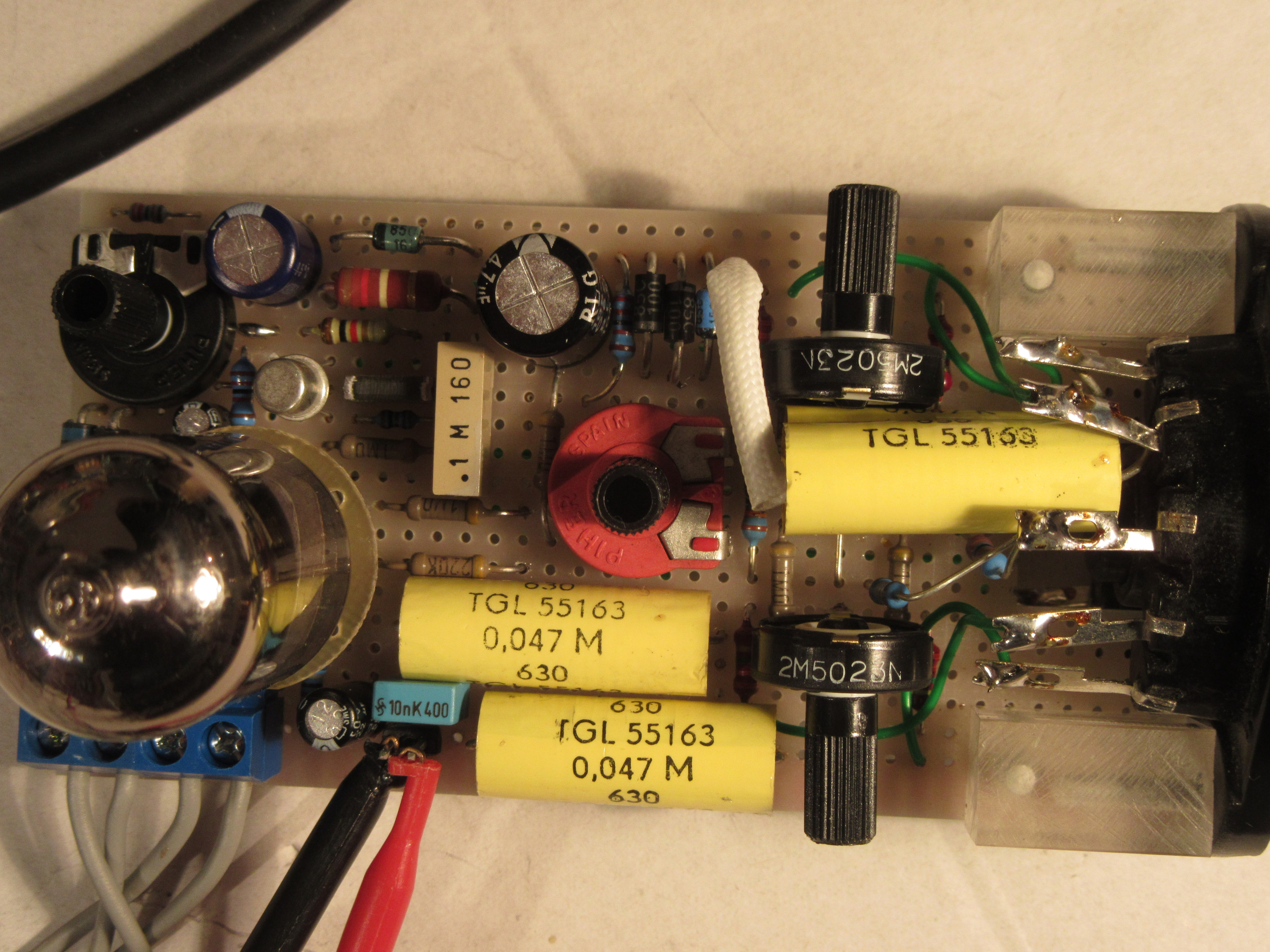
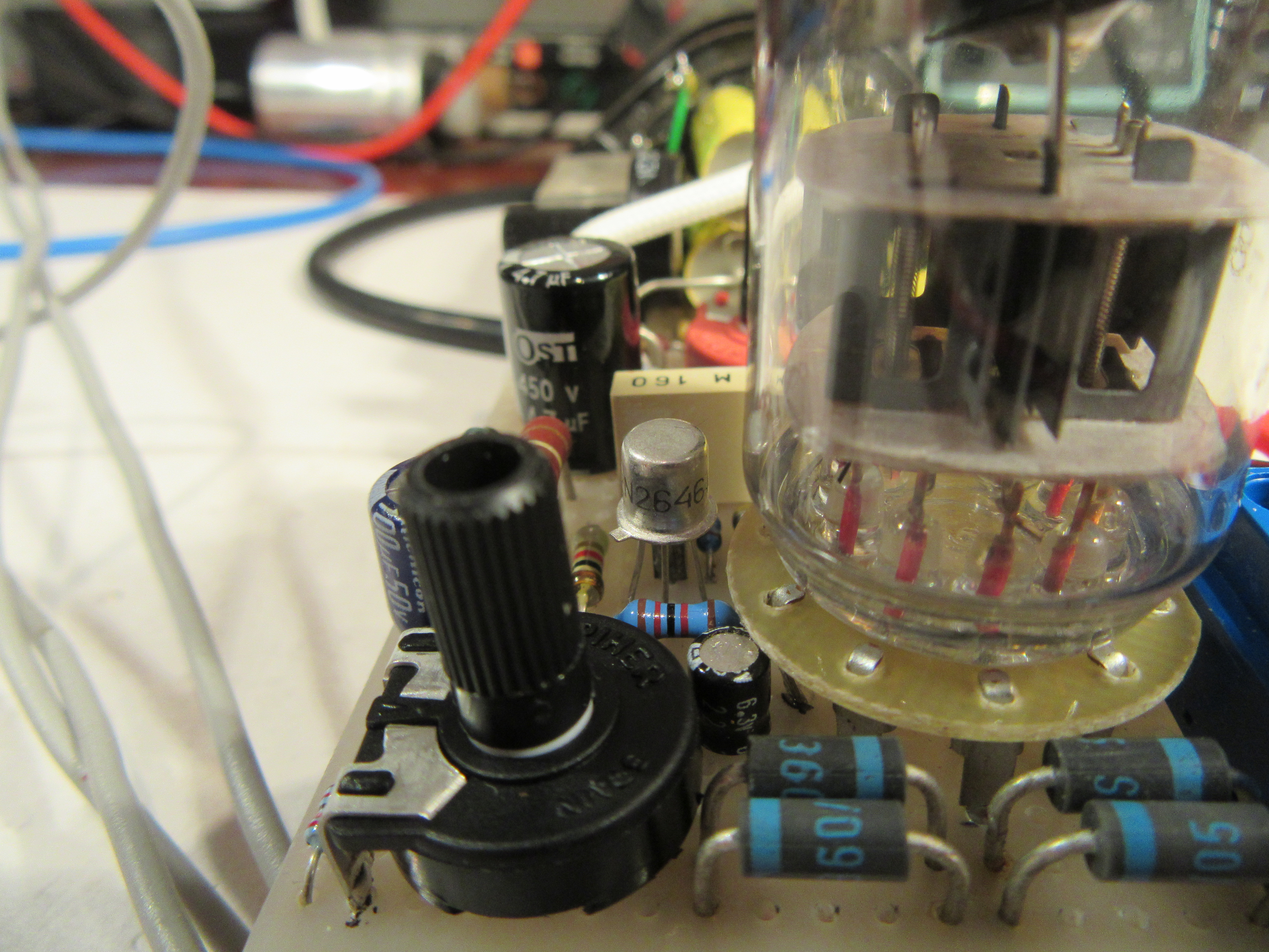
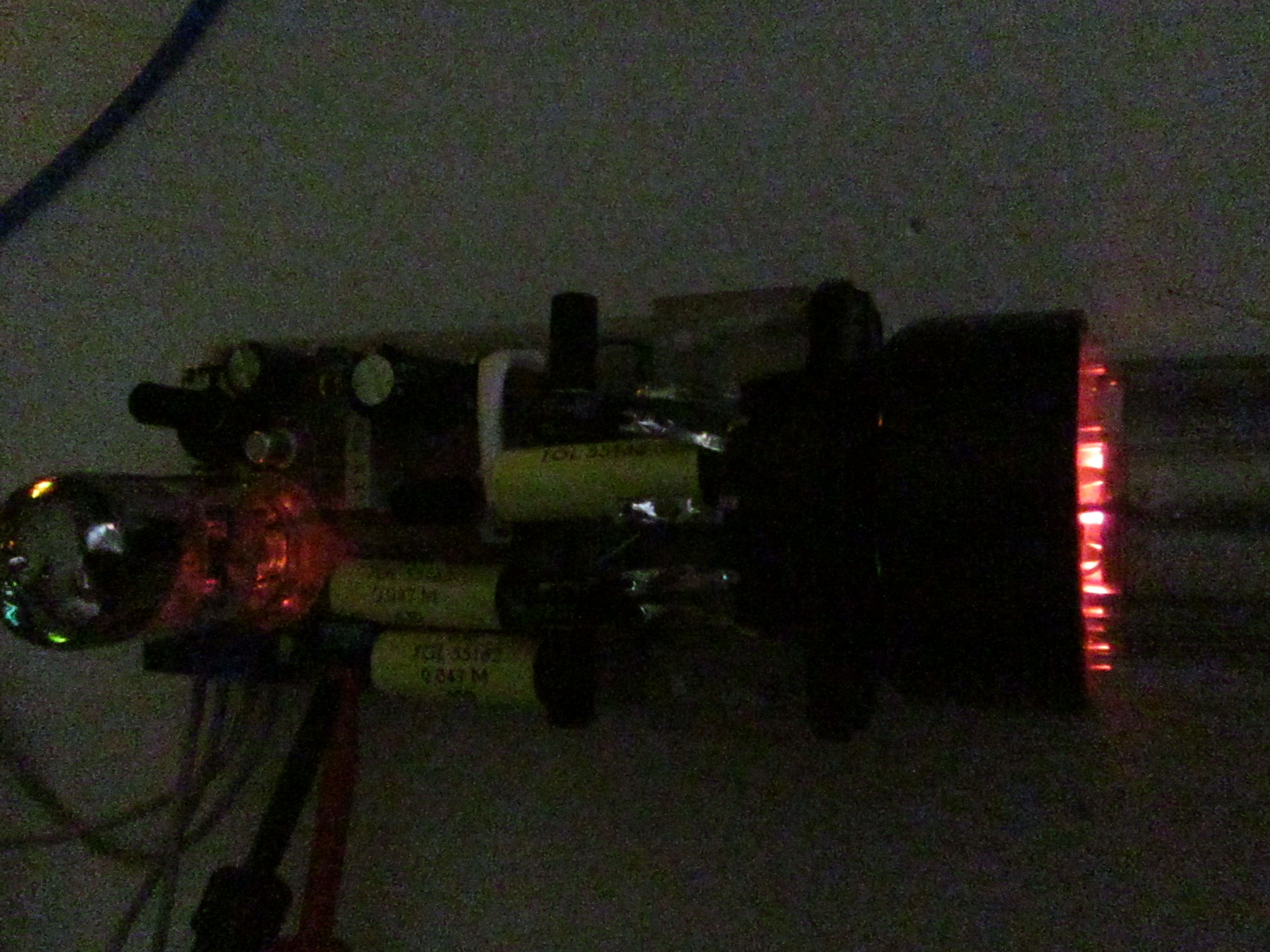
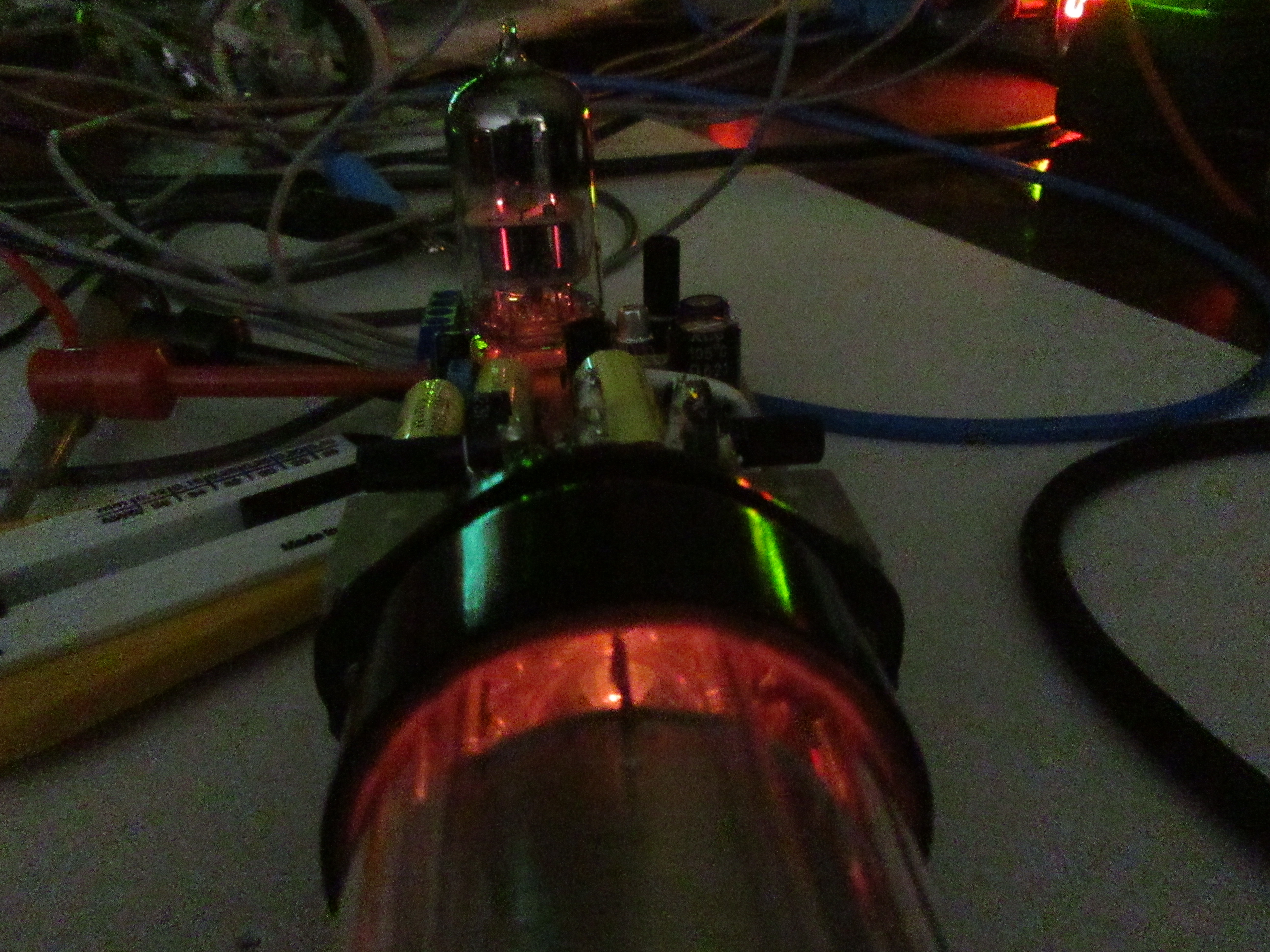
Mini Oscilloscope Electronics
Sawtooth generator with unijunction transistor 2N2646
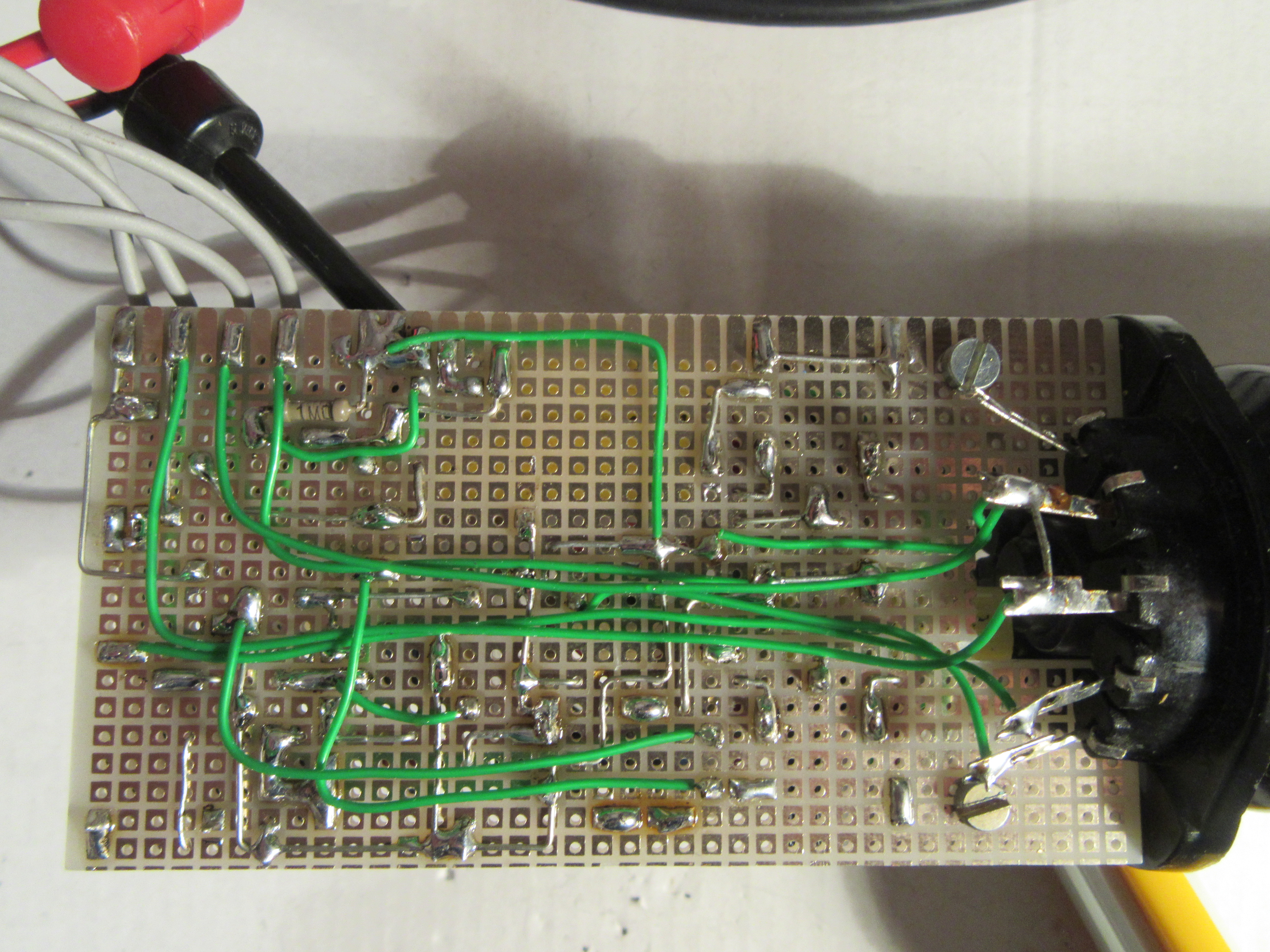
Mini oscilloscope electronics from below
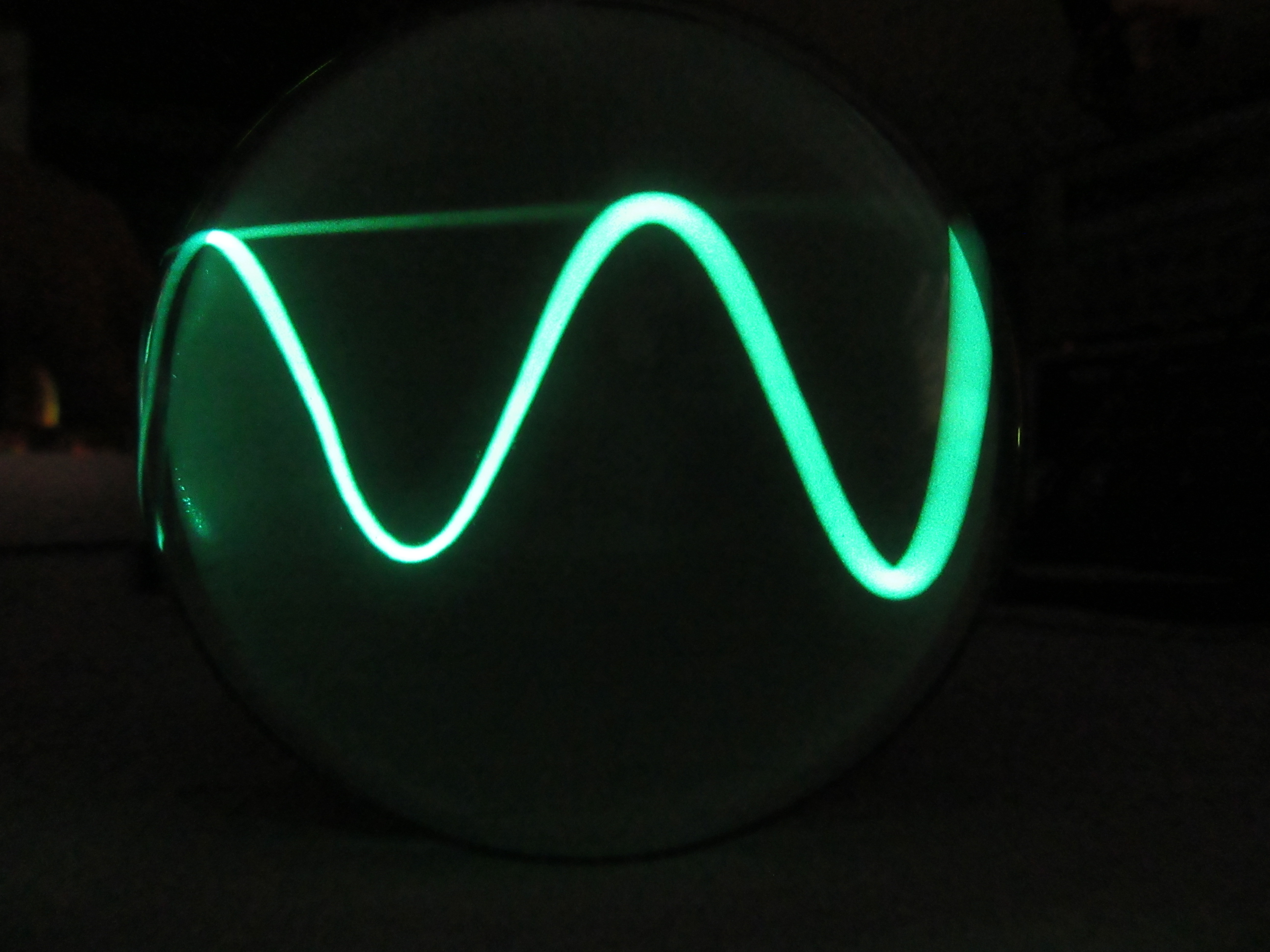
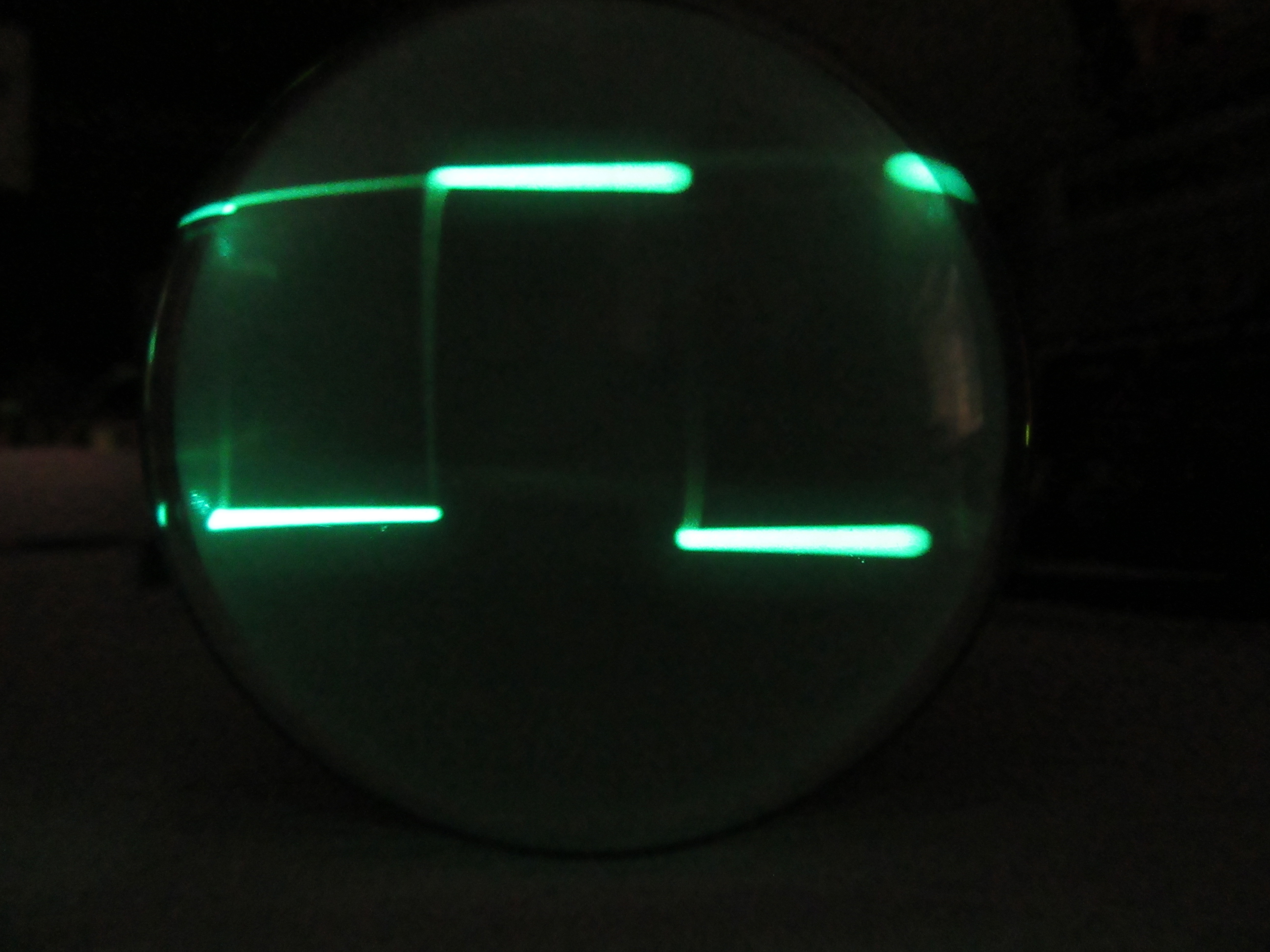
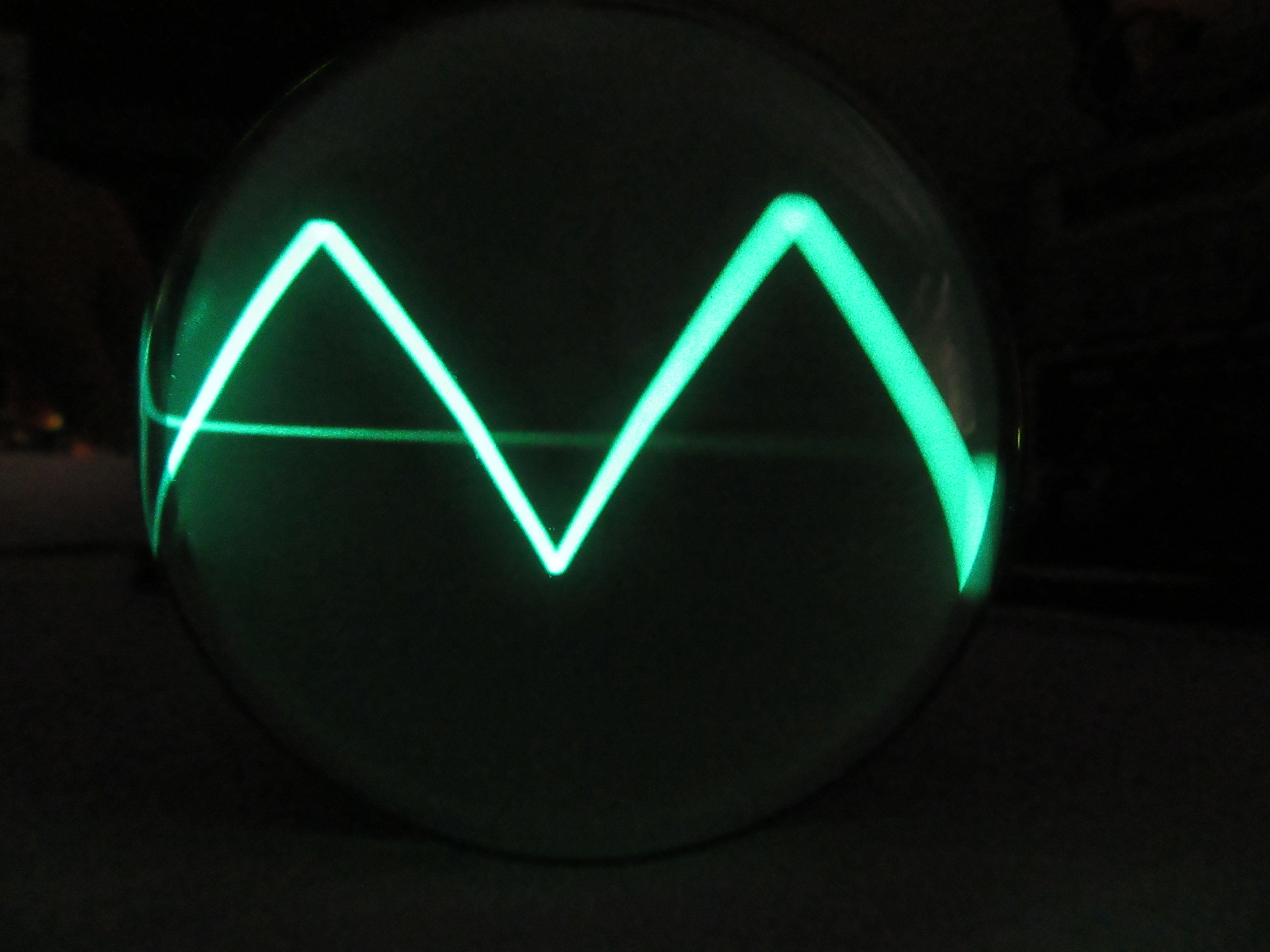
Sine, square and triangle signals approx. 2kHz from my function generator.
The tubes glow.
This is what the whole thing looks like live, fed from the function generator.
A small oscilloscope, a Picoscope EO1/7 is in my possession for a long time. When I bought it maybe 20 years ago for nostalgic reasons for little money, I got an extra chassis as a spare parts donor with it. This chassis was rusted, bent, some parts were missing or broken. Of course, there was no tube left either.
During a cleanup this spring, this chassis was supposed to go into the scrap. Before I had the heart to do that, I made an inventory:
all tubes incl. the picture tube are missing
selenium rectifier missing
no front panel and no case
rust and dirt on all parts
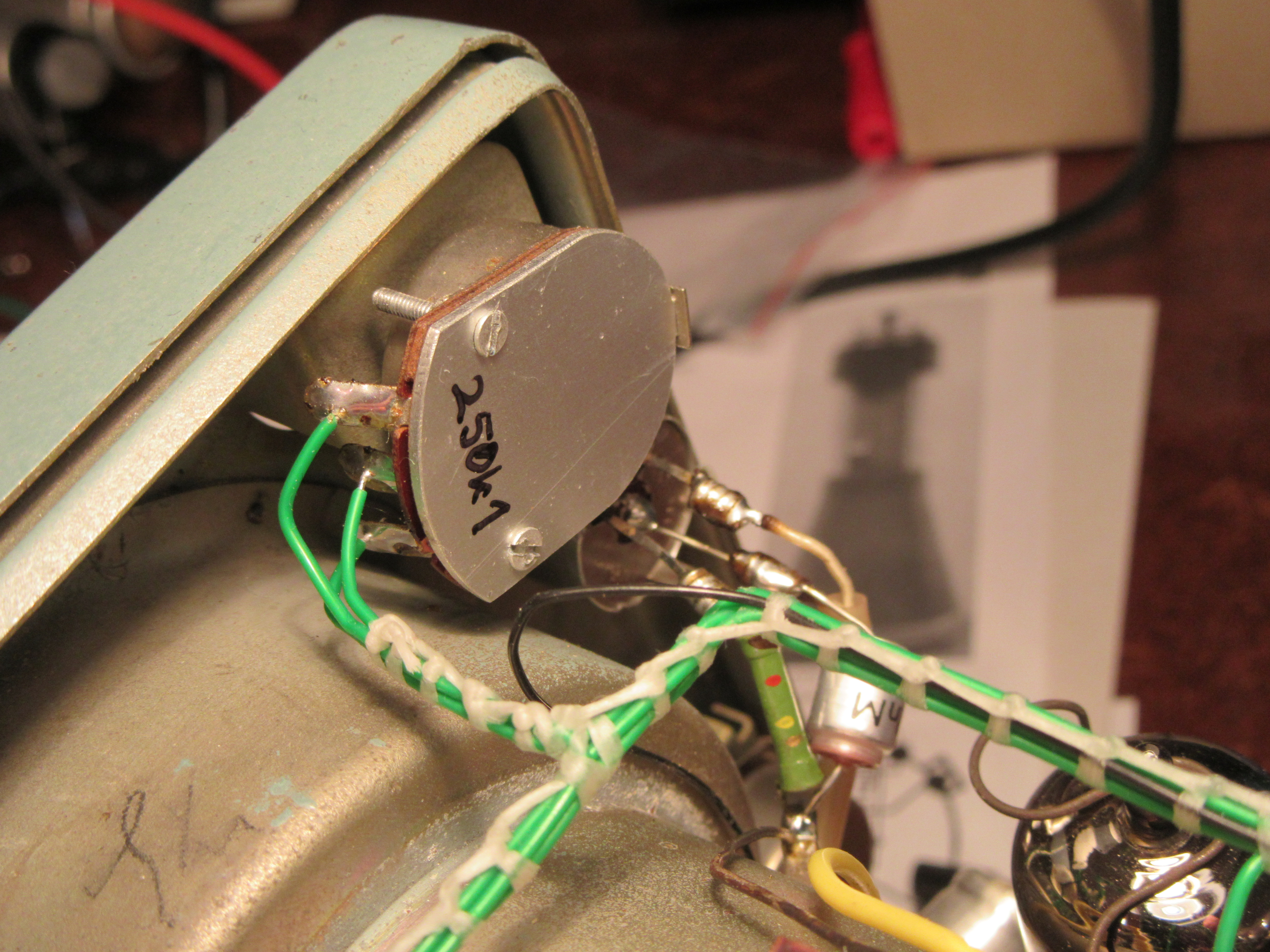
potentiometer with power switch, mechanics bent, Bakelite switch housing broken
potentiometer rear cover missing
fuse holder incomplete
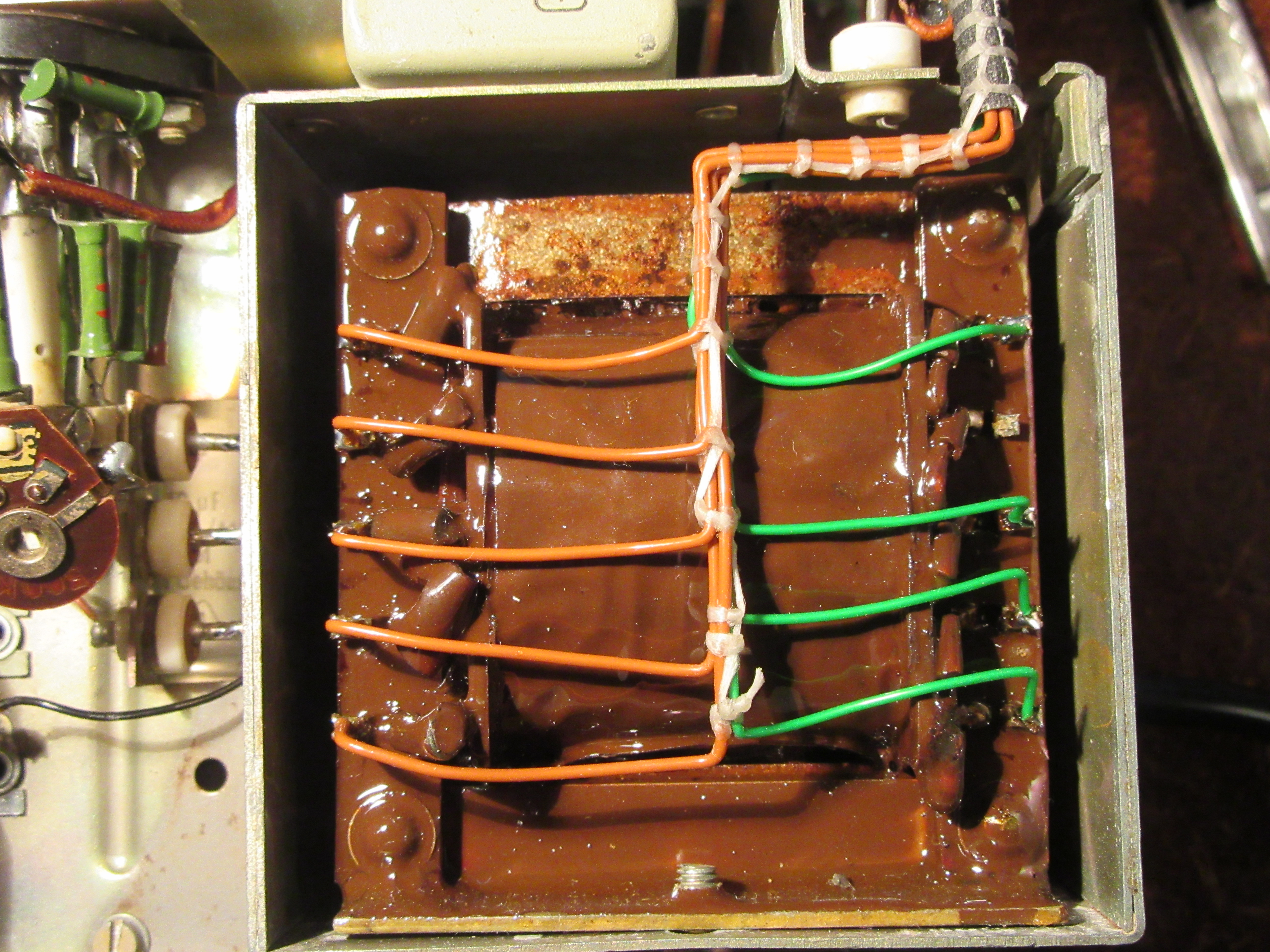
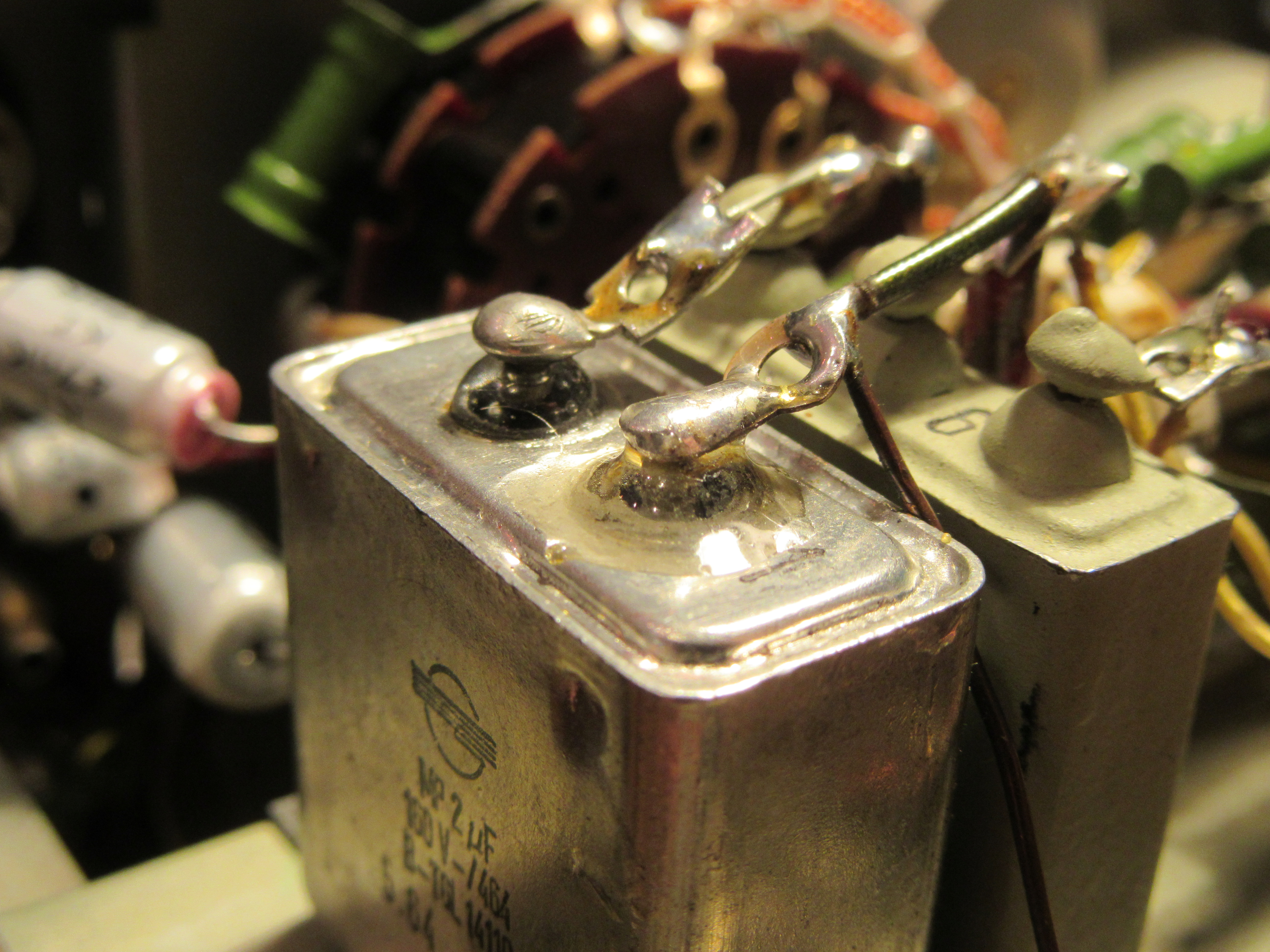
MP condenser one terminal broken, oil leaking out
wiring harness partly removed by brute force
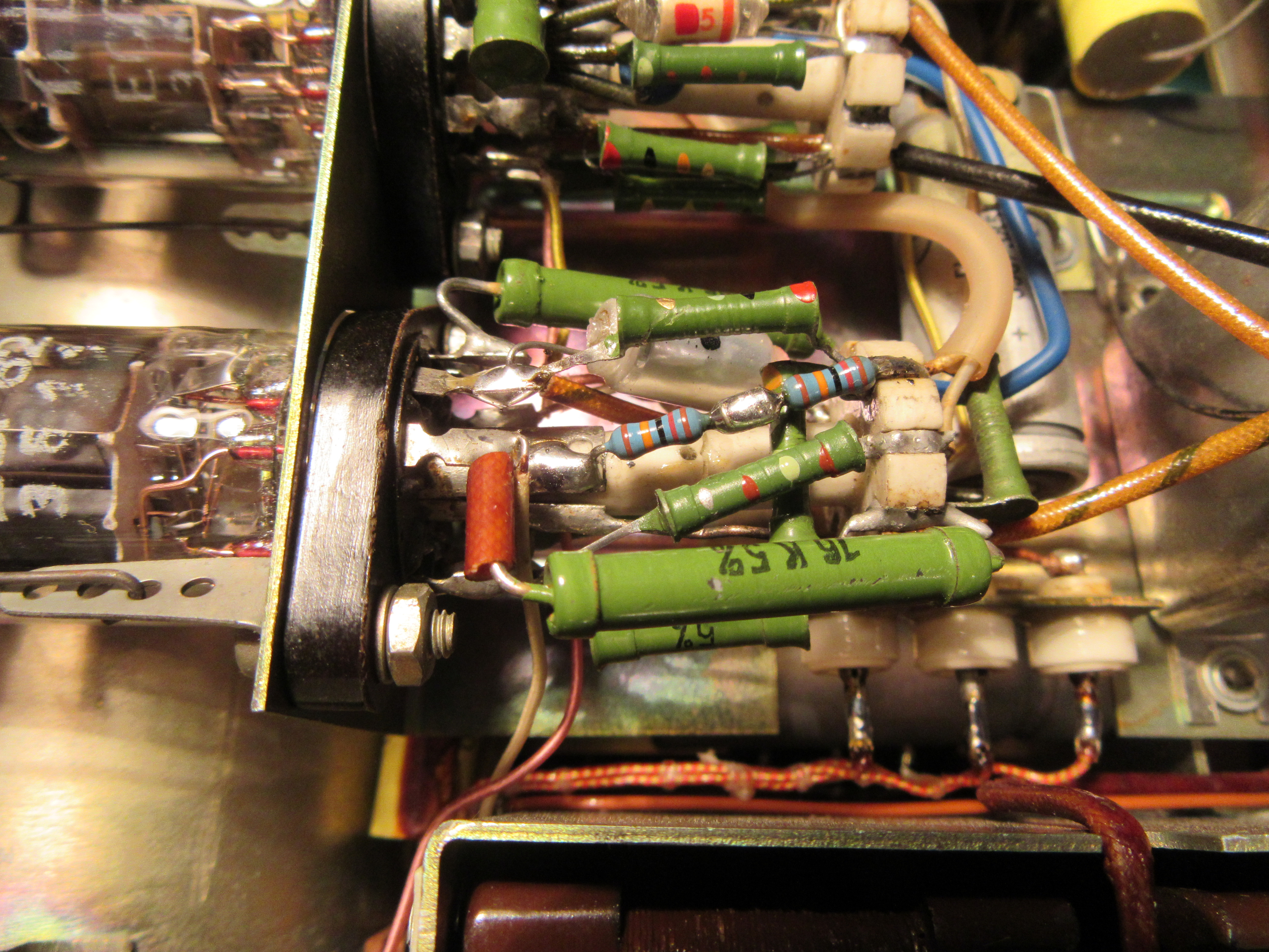
one ceramic tube socket broken
two resistors destroyed
few capacitors missing
But the power transformer, the filter choke and a smaller high voltage transformer were apparently still intact. Furthermore, both rotary switches for X and Y were OK. These are quite good conditions for a rebuild I thought. Unfortunately I didn’t take a picture of the original condition. It really looked like a pile of junk.
The beginning
First, I disassembled the unit as much as possible, cleaned it properly and partially derusted it. After derusting, I sealed the power transformer with an alkyd resin lacquer. Basically you should use a high voltage insulating varnish for this. Since this is not so easy to get privately, it does also e.g. a good colorless boat varnish as in my case.
The next step was to repair the defective components. The leaking MP capacitor got a new terminal lug, luckily a small piece of the old terminal was still sticking out. After that, the thoroughly degreased connection was sealed with epoxy resin.
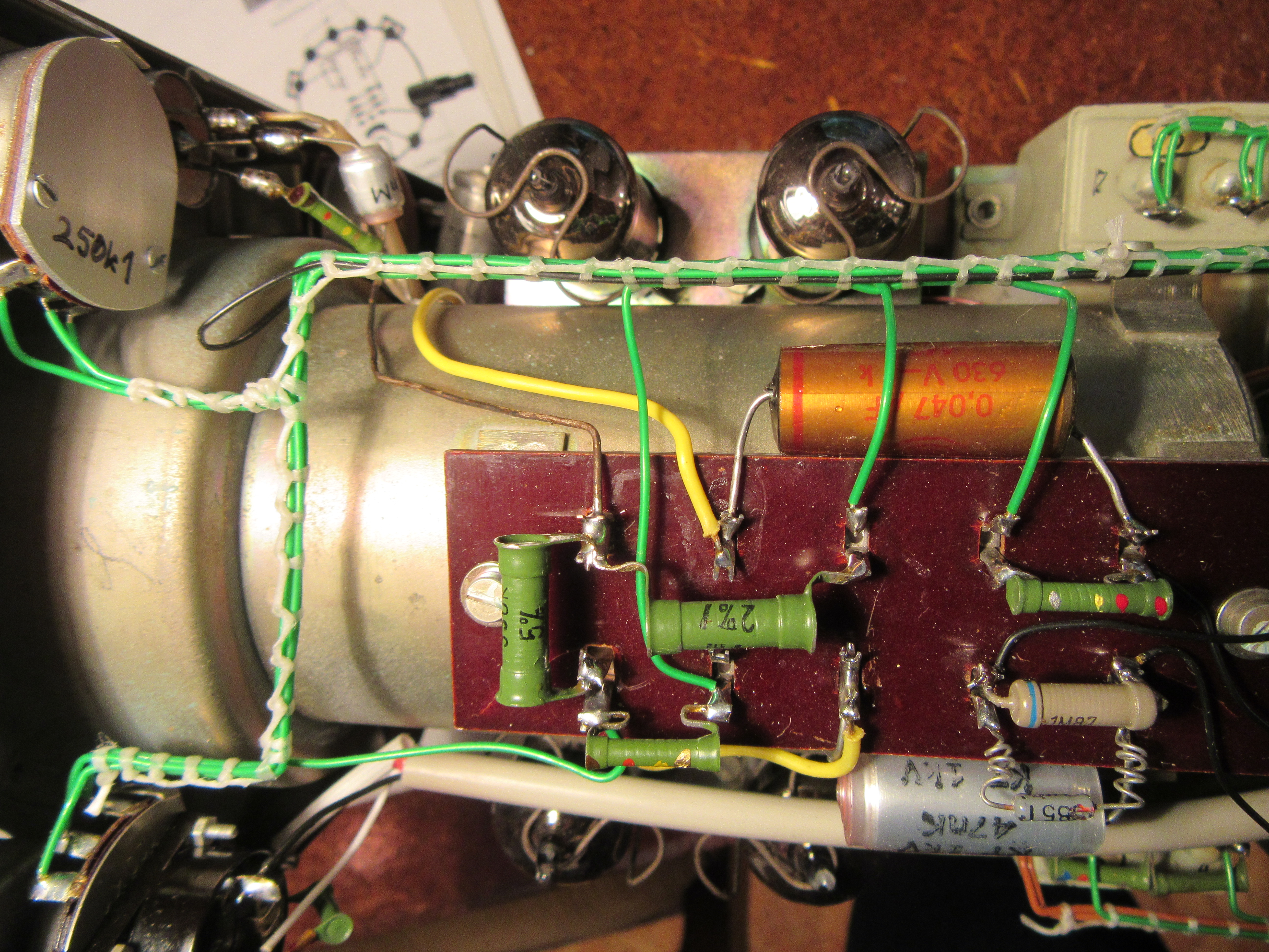
I also glued the broken tube socket with epoxy resin. In the picture you can see that behind one of the two replaced resistors.
It is important to use the “normal” epoxy resin for bonding. This is resin and hardener, which you usually have to mix in a ratio of 100:60 to 100:40. The curing time is 24 to 48 hours. There are also all kinds of fast-curing epoxy-based adhesives. In my experience, however, these do not adhere as well to ceramics and Bakelite.
Bakelite is the keyword for the next repair, the potentiometer with the power switch. Here I could straighten the mechanics again. Fortunately, all fragments of the switch housing were available. Bakelite can also be glued excellently with low viscosity epoxy resin. Afterwards, the glued area is usually more stable than the rest. After cleaning, lubrication and contact care with Neo-Ballistol, the potentiometer works like new again.
Lastly, I made a new rear cover for the second defective potentiometer. In contrast to the original, I made this from aluminum instead of sheet steel. Thanks to my electromechanical training in the 80s, I can do such work relatively precisely.
This saved the components that could be saved. The function of the two defective pots is completely restored and because of the presumably better lubrication, the expected service life is possibly also longer than with the original.
Spare parts
Some spare parts I had to order. The fuse holder is a standard model from the GDR and still relatively easy to find on the Internet. From the tubes ECF82 I was able to purchase a lot of 8 pieces very well preserved copies from Telam at a good price. It was important to me that all tubes are one make. I think this is a good idea for metrology.
A bit more difficult was to get a cheap picture tube, the B7S1. The offered ones were too expensive for me and that with uncertain function. By chance, I came across an O7S1, compared the base scheme and characteristic values and was of the opinion that the O7S1 is a direct predecessor of the B7S1 from the time before 1945. In the end, I had to find out that this is not so. The base is turned by 180°, the cathode is not led out individually and the three grids have also somewhat different functions. I described the test of this tube in a separate blogpost. So in the end I had to look for a B7S1 and with some luck I found a new and original packed one, even the warranty certificate was still there.
Reconstruction
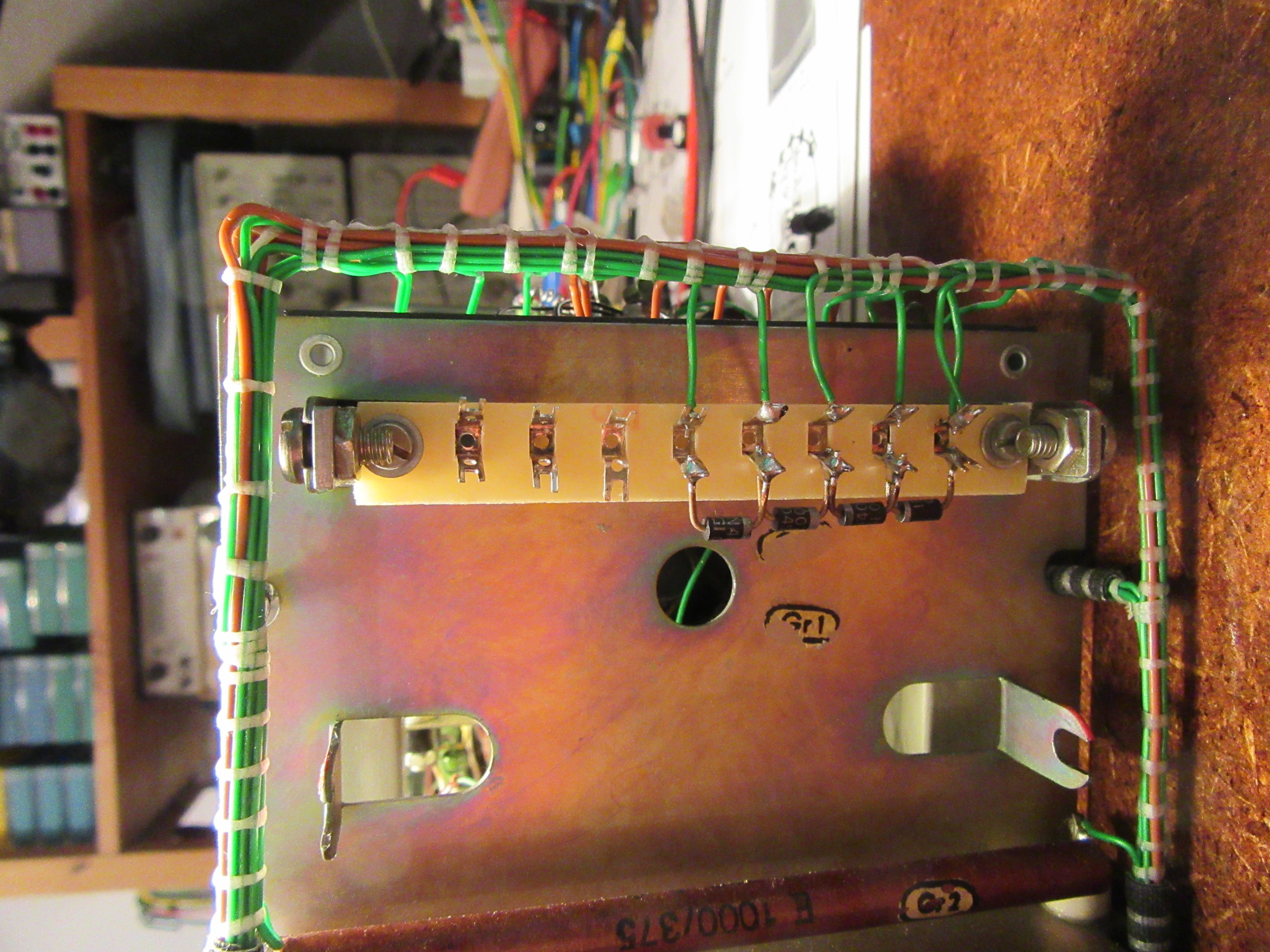
First I dedicated myself to the power supply. Also to test first if everything is ok with the hard to repair transformers. Unfortunately the selenium rectifiers were missing and I had to replace these two two-way rectifiers then by four diodes 1N4007 in bridge circuit.
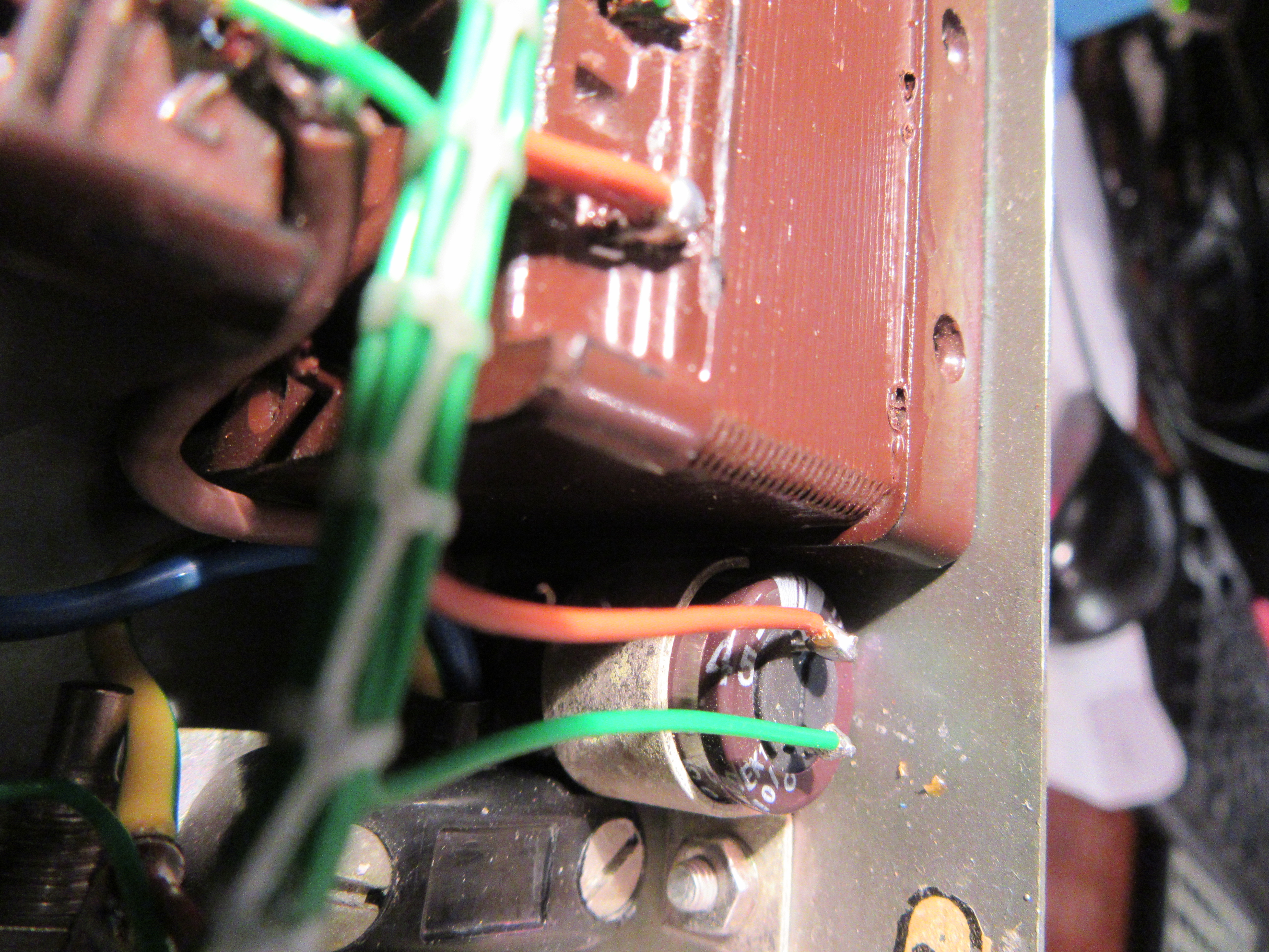
Also, the wiring harness of the power supply was completely missing. I rebuilt it pretty much original. However, instead of the double-wound wire, a modern alternative with ETFE insulation was used. I dedicated a whole blogpost “The wiring harness” to this wiring variant. Of the two electrolytic capacitors in the power supply, one axial 10µF/350V was unsalvageable due to a broken connection directly at the case. In its place, a modern radial variant with 450V dielectric strength is now doing its job.
I reformed the 50µF/350V cup capacitor within two weeks. This worked wonderfully, at nominal voltage it had only 80µA leakage current at the end. I have dedicated a whole article to the forming of electrolytic capacitors.
Unfortunately I did the first test of the power supply without load. Because of this and the lower voltage drop of the new rectifier bridge made of silicon diodes, the anode voltage had about twice the nominal value at no load. It went poof briefly and the elaborately formed cup electrolytic capacitor was history, really a pity. At least I learned that you should never test power supplies of tube devices without load and how to restore a cup capacitor or how to hide a modern capacitor in it. There will be a post about that here soon, too. After this repair the power supply was complete and worked perfectly.
The next step was to restore the other wiring in the unit. In addition, a total of two defective resistors had to be replaced.
I have exchanged all paper capacitors for safety reasons and replaced them with film capacitors. I was lucky and was able to replenish my supplies thanks to Markus from Hamburg, who offers many different values at “ebay Kleinanzeigen”. But I felt too sorry for the basically still working paper capacitors to throw them away just because they have a slightly too high leakage current. I documented my attempt to make them fit again in the article “Paper capacitors restore“. This is certainly better than replacing them, since some of the circuitry is designed to handle these higher leakage currents.
Finally, I just put in the four ECF82 tubes and the picture tube, and voila, everything worked flawlessly right away. Now the front panel and the case are missing and at the end the picture tube should show the time in analog form. But that’s a new project.