Anyone who has read my article “Weekend project: bat detector” will have heard, that I was not fully satisfied with the result. The device is working but it’s too insensitive. This induced me to start from scratch and build it again. This time with digital technology which is better prepared for the task. The electronic key component is a dsPIC33E, a microcontroller with DSP functions from Microchip.
The Goal
The idea is to record the ultrasonic signal with microphones which are sensitive in the needed frequency range. Subsequent the amplified signal will be AD-converted with a sampling rate of 300kHz at least. After a spectral analysis with FFT the spectrum is indicated at a display. If possible the signal will be rendered audible by an inverse FFT after changing the sampling rate. This procedure should transform the gamut of the signal to lower frequencies, hearable for humans. As far as this coarse ideas become real and the project grows with all hardware, software and mathematics, I will certainly write something about it in this blog.
The Experiment
Initially I need a small system for digital signal processing. A preamp and signal conditioner at the input, AD-converter, a DSP or a fast microcontroller and at the end of the chain a DA-converter. The system shouldn’t lack a small display too. Nice to have would be a battery power supply and additional supply by USB.
Component Inquiries
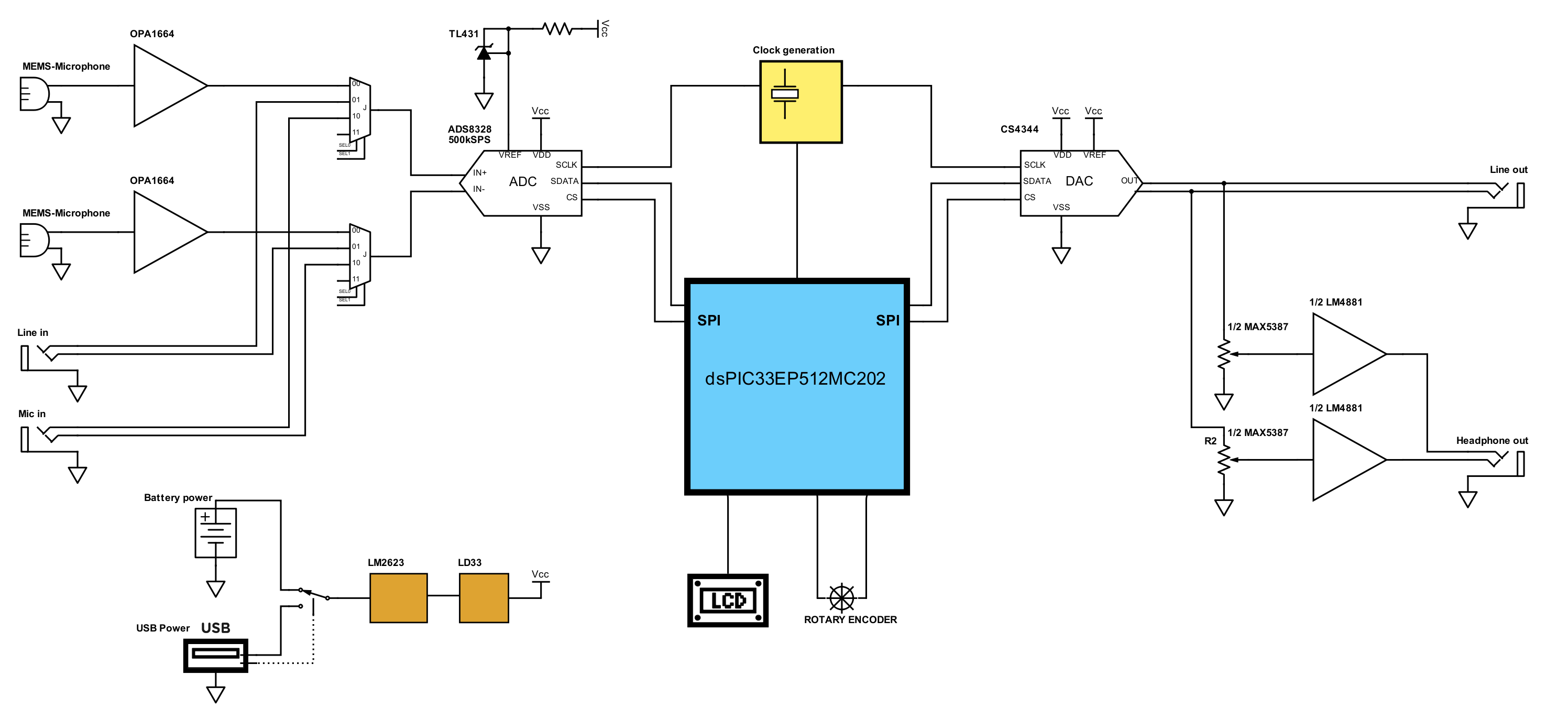
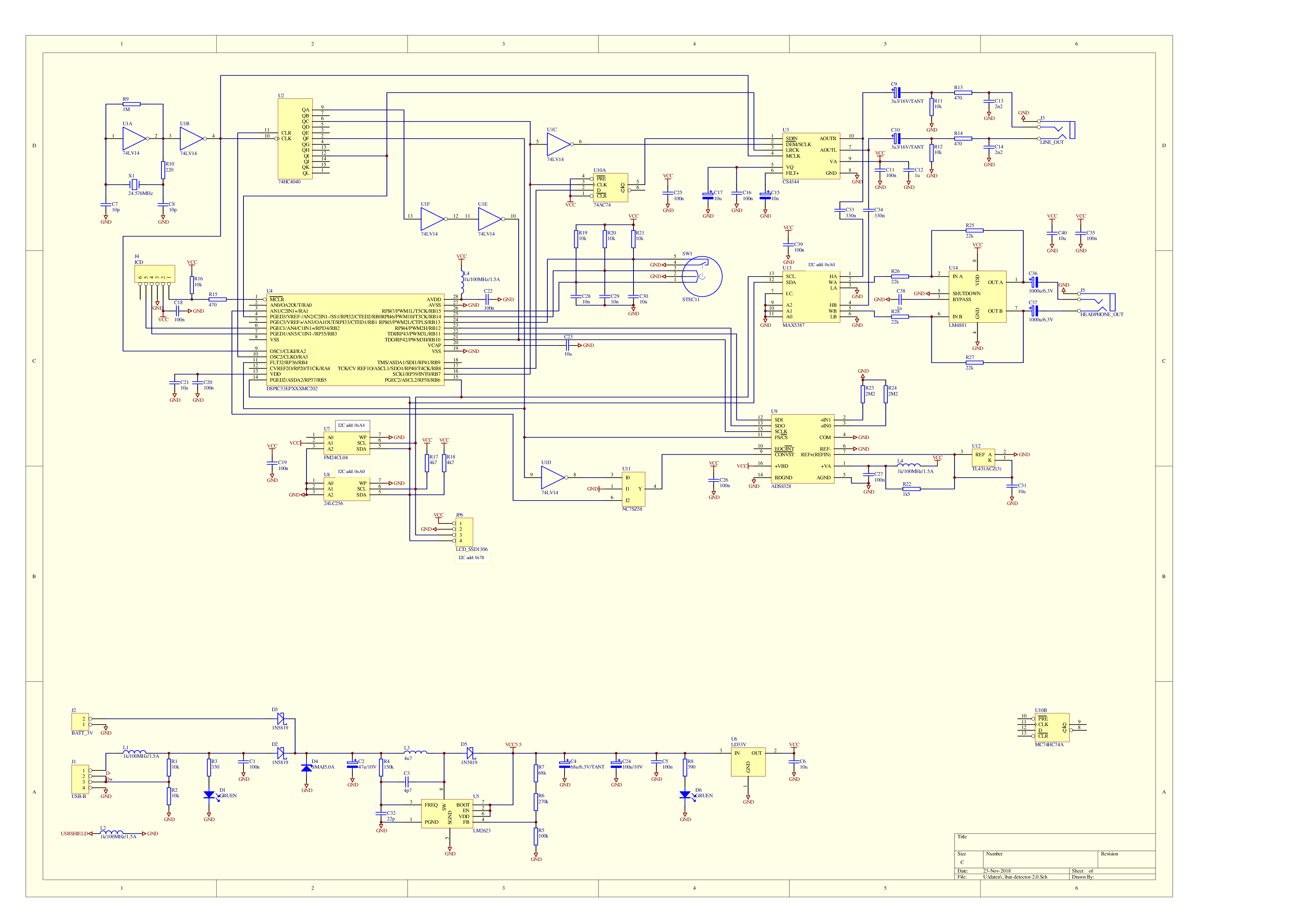
Every time a project like this one starts with investigations on the components to use. Which microcontroller will be chosen, what kind of converters to use, how to build the power supply et cetera. These considerations leads to a pretty detailed block diagram as shown above.
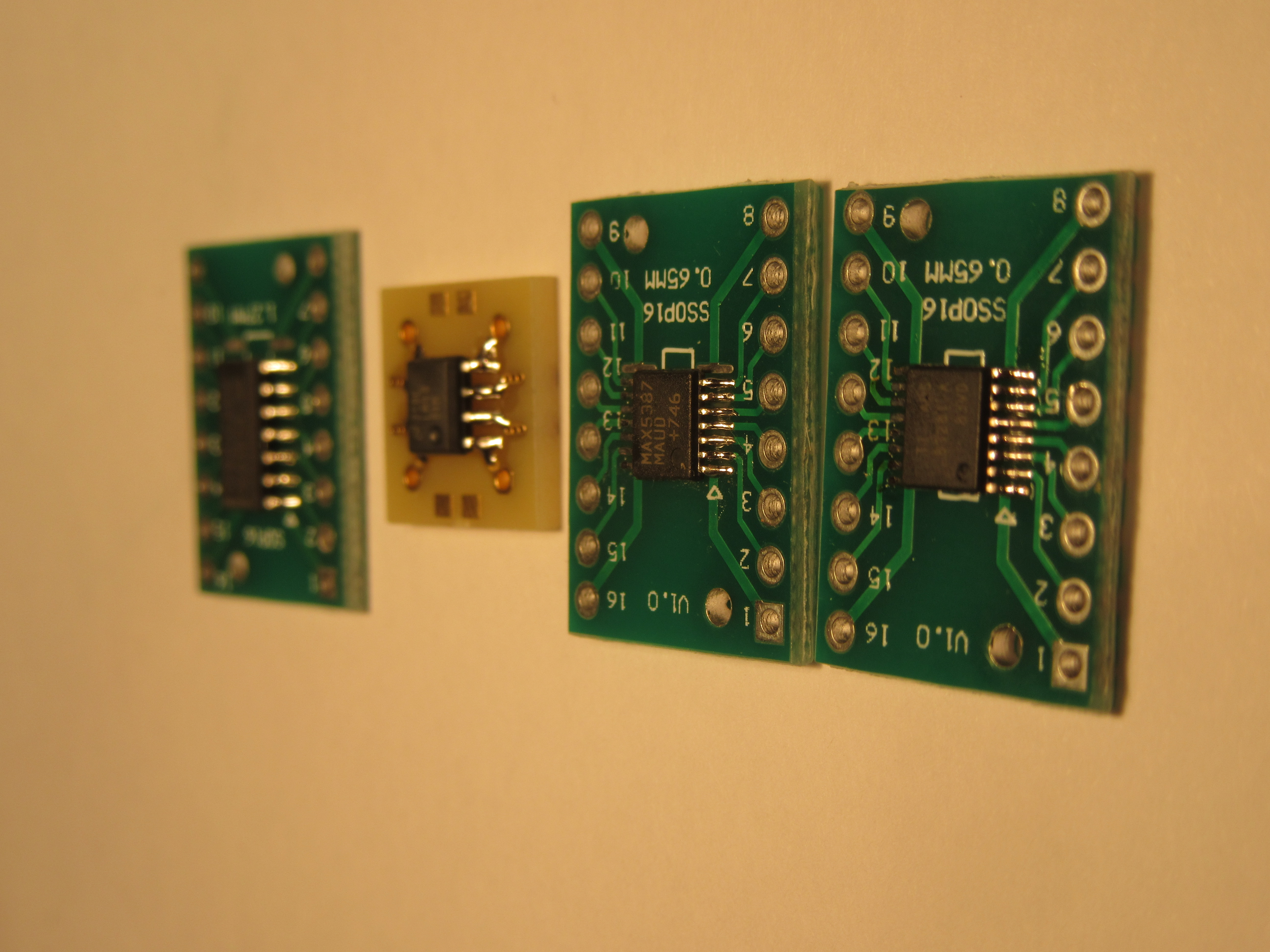
Unfortunately some special components are not sold in small quantities and often only an B2B (business to business) selling platforms or with very high shipping costs. The DSP for instance I had to order as a sample directly at the manufacturer. At all I needed to place 3-4 orders. Because of SMD cases of some chips I had to solder these on small adapter boards to use the chips in my hand soldered prototype design on a stripboard.
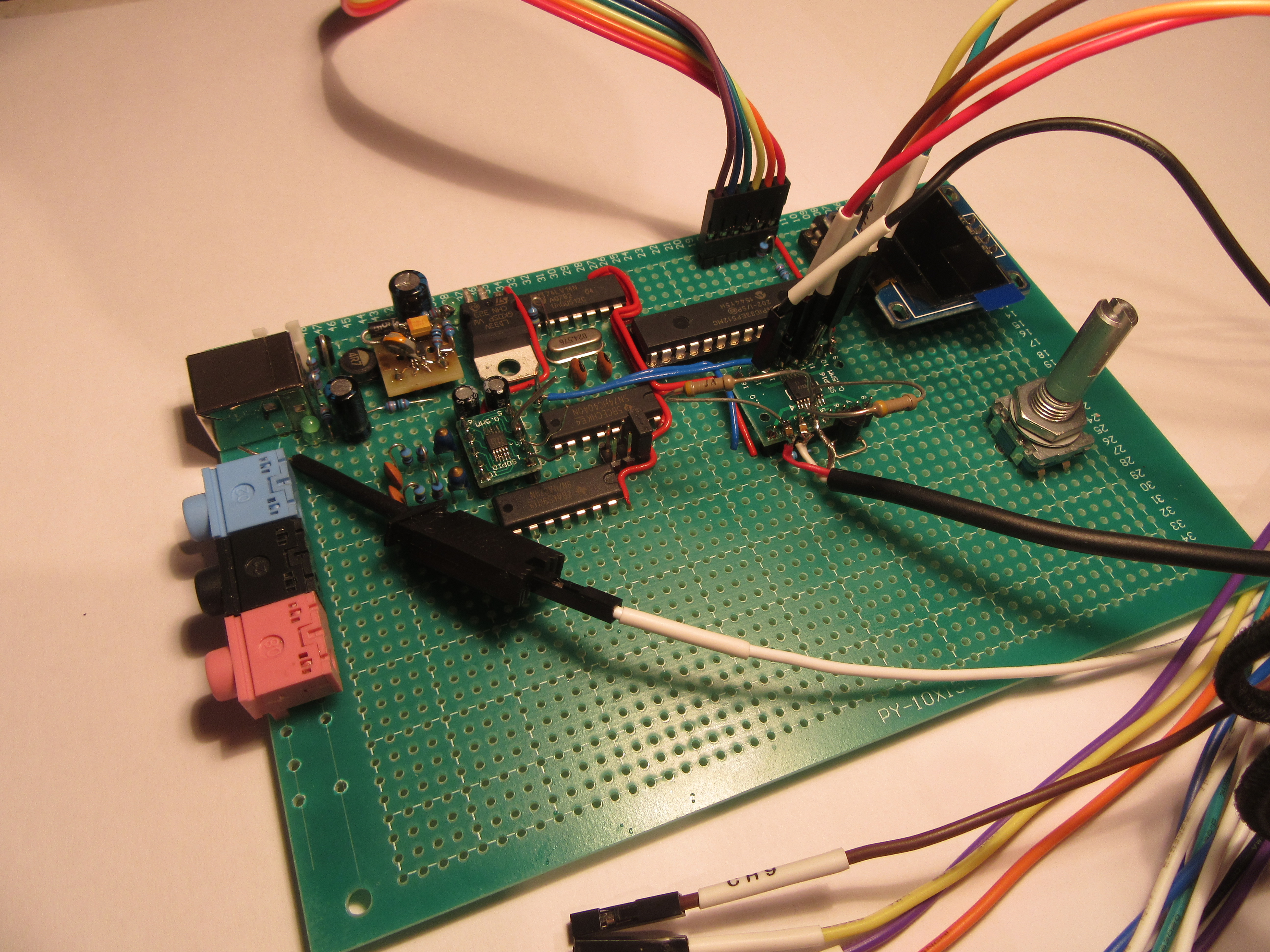
Prototype
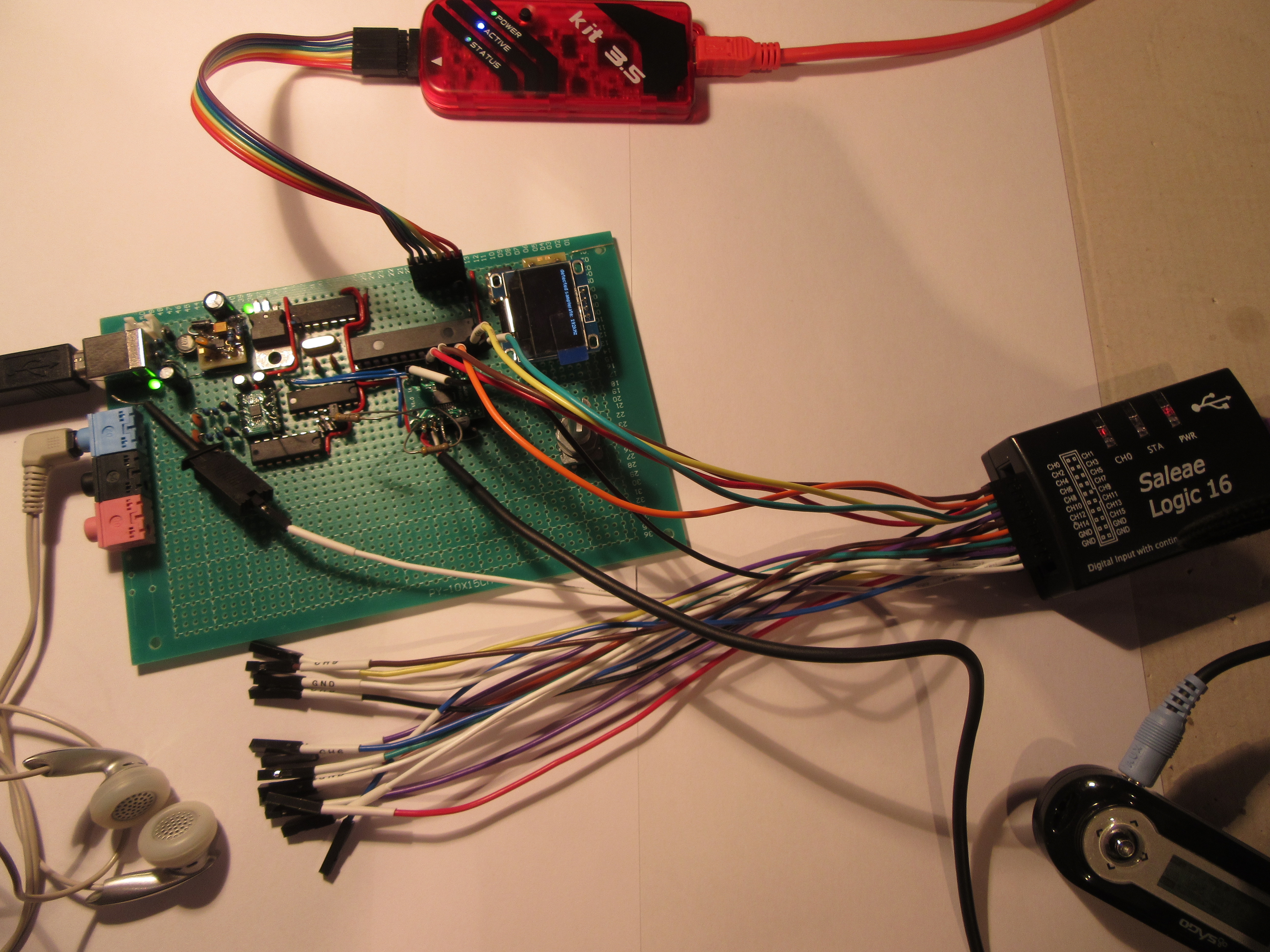
The orders arrived and some tinker evenings later the prototype was ready for some tests. I always do this step by step for each component.
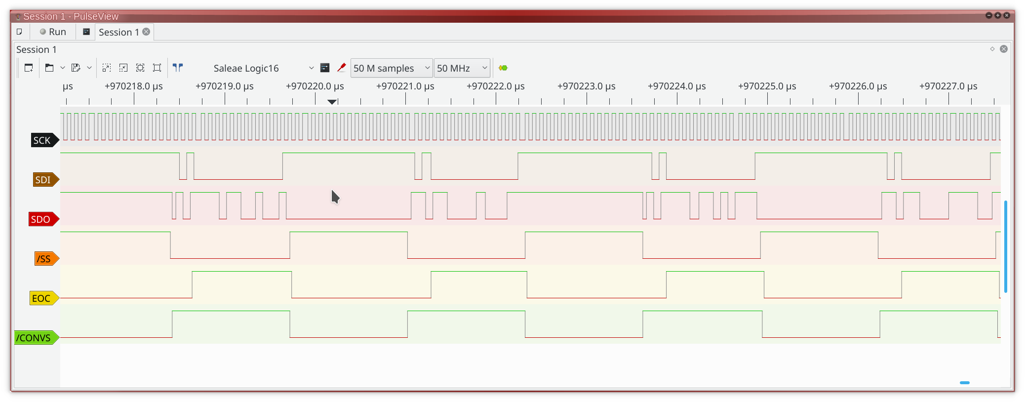
Starting point was the oscillator, followed by the I2C bus, the OLED display and the AD/DA-converters. At this step I faltered. Every time it is fiddly to bring an SPI (synchronous serial interface) to work, especially at high data rates and if the default configuration of both sides does not match. To solve the problem I had to buy a new logic analyzer with 100MHz resolution. Root cause was the need of a signal /CONVST (conversion start) to trigger a conversion at the AD-converter. The CPU wasn’t able to generate this signal fast enough and especially not synchronous. As a way out I used the inverted signal /SS (slave sync) of the SPI as /CONVST. Conversions should anyway run synchronous to the SPI transfers which implies one transfer (/SS) follows one conversion (/CONVST).
To analyze the electrical signals during data transfers I use PulseView, an awesome open source software for logic analyzers including some amazingly cheap devices like Cypress EZ-USB FX2 based ones.
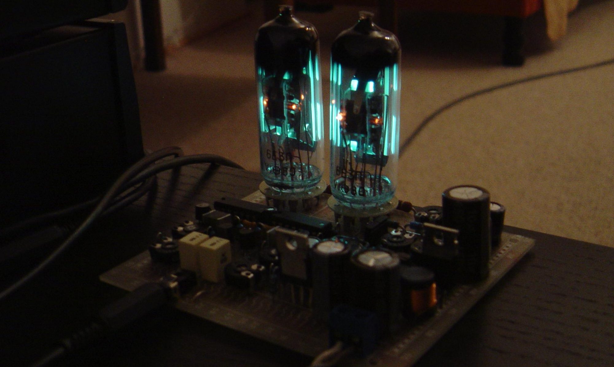
After sailing around some difficulties with hard- and software it was a terrific moment to hear the first synthesized distortion free sinus tone.
Software
The software is mainly written in C. An integrated development environment, “MPLAB® X“, is provided by the CPU manufacturer which is freely available but has some limitations. More than an “-o1” is not allowed and leads to comparatively slow code. This is no problem at all here, time-sensitive parts are simply implemented in assembler.
By the way a tip for all users of GCC, AVR-GCC etc: It’s quite easy to integrate assembler code in C. Just add a file with “.s” or “.S” extension to the project and add your assembler code there. The file with the capital s extension will additionally handled by the preprocessor.
The latest version of the software is published on my Github-Account.
Hardware
The hardware is not yet perfect but good suited for further experiments. After all the system is able to process the input with 16bit at 384kHz mono or 192kHz stereo sample rate and output simultaneously 24bit at 192kHz stereo sample rate. At the same time the CPU is busy by a few percent only due to DMA transfers.
Anyway for the next prototype some things I will improve, primarily to simplify the SPI programming.
- dsPIC with I2S interface
- dsPIC with at least 3 SPI interfaces and more IO ports
- bigger and colored display
- additional RAM, may connected to SPI port
More RAM would be great. The maximum on chip memory for dsPIC33 CPUs is about 50kBytes. A dsPIC33EP512GP806 in a TQFP64 case could be a good fit, a 32bit controller like the PIC32MZ1024EFH100 might be an excellent choice too.