Bluetooth Audio Receiver with PCM5102A

Bluetooth Audio Receiver mit PCM5102A

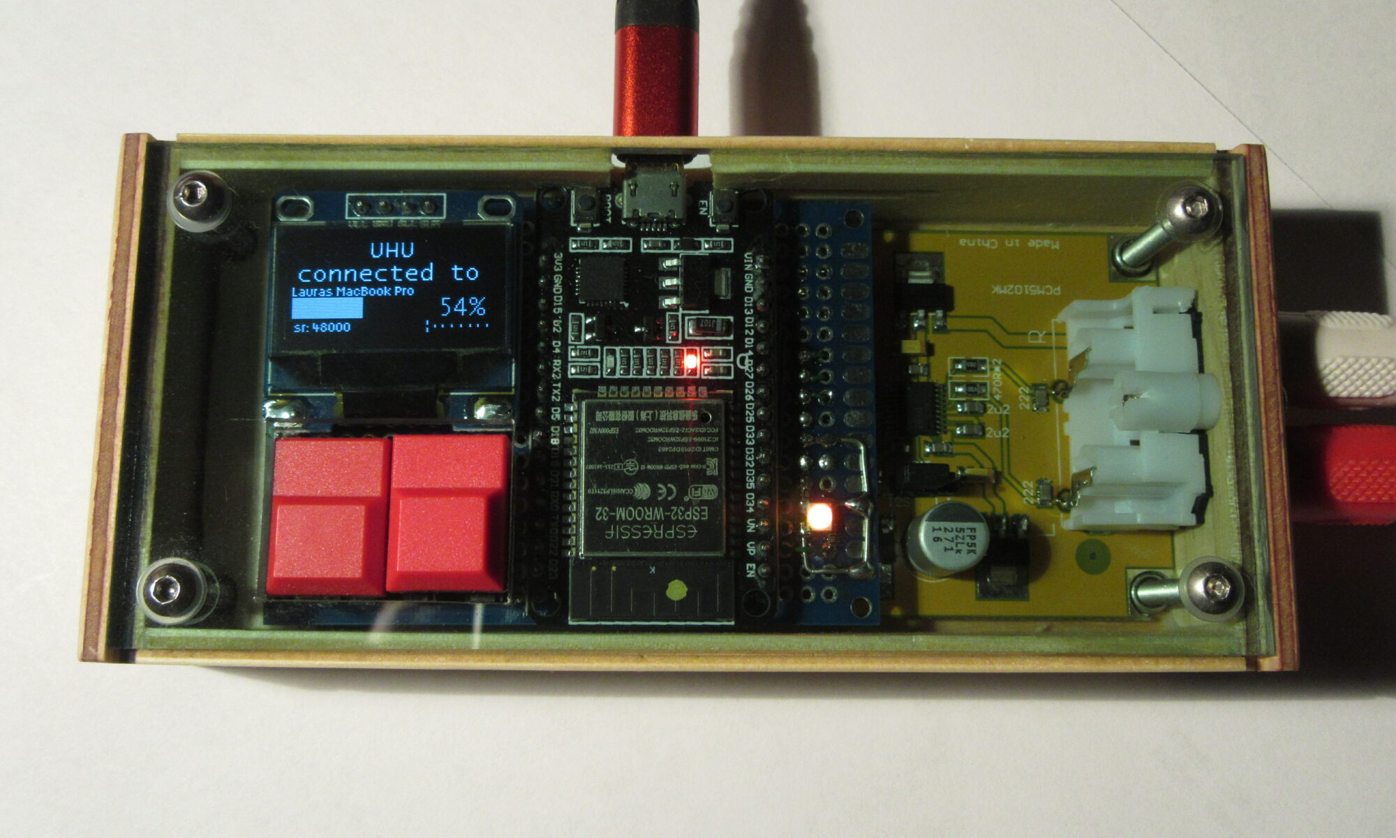
We have a receiver in our living room that is almost exactly 50 years old. The Sony STR-V5 has a lot of oomph, is wired with wire-wrap connections like earlier space technology and will certainly work for another 50 years. The only problem was that its cinch inputs are no longer compatible with current devices that transmit wirelessly. This gave rise to the idea of building a slightly better Bluetooth receiver for the Sony with a matching retro look. The end result can already be seen here.

Receiver betriebsbereit
receiver ready

Bluetooth-Audio

Before this project, I had no idea about bluetooth. In my mind, it sounded pretty easy to transfer the audio and then play it back. Unfortunately, it’s not quite like that. Due to the limited data rate of a Bluetooth wireless connection, the data must be compressed. A “codec” does this. Of course, it has to be the same on the sending and receiving side. The oldest and currently the most widely used codecs are “AAC” and “SBC”. Audiophile users were not satisfied with the quality of this compression, so a number of new standards are trying to enter the market. In addition to “SBC” and “AAC”, “aptX”, “aptX HD” and “LDAC” are now also competing for the customer’s favor. Don’t forget: sender and receiver must support the same codec. For example, if you buy Bluetooth headphones with “aptX”, but the receiver speaks “LDAC”, only a connection with “SBC” is established, if it works at all.

Overall, the Bluetooth standard is quite complex and my interest in delving further into it is limited. The software uses “SBC”, which is supported by almost all devices.

Volume control

While programming, I noticed that the volume control with Bluetooth is the crux of the matter. The basic problem is that the audio samples are transmitted with 16 bits and usually 100% volume. In the receiver, the volume is now reduced to say 35%. That means we have to divide the audio samples roughly by 16. As a result, we have audio data with a resolution of only 12 bits. And that’s exactly how it sounds.

A simple solution to the problem is a 32 bit D/A converter. The received 16 bit samples are converted into 32 bit values ​​by simply adding zeros. It doesn’t make a difference at first. In the second step, however, we can calculate the volume with the 32-bit value and then send it directly to the D/A converter. As a result, there is no loss of information at low volume, the 16-bit information is retained.

I recently wrote an article about the secrets of a pleasant volume control.
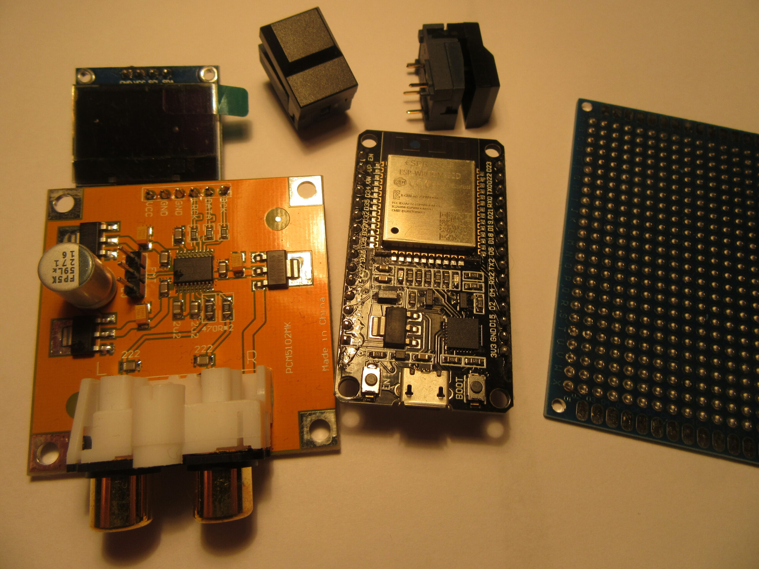
Components

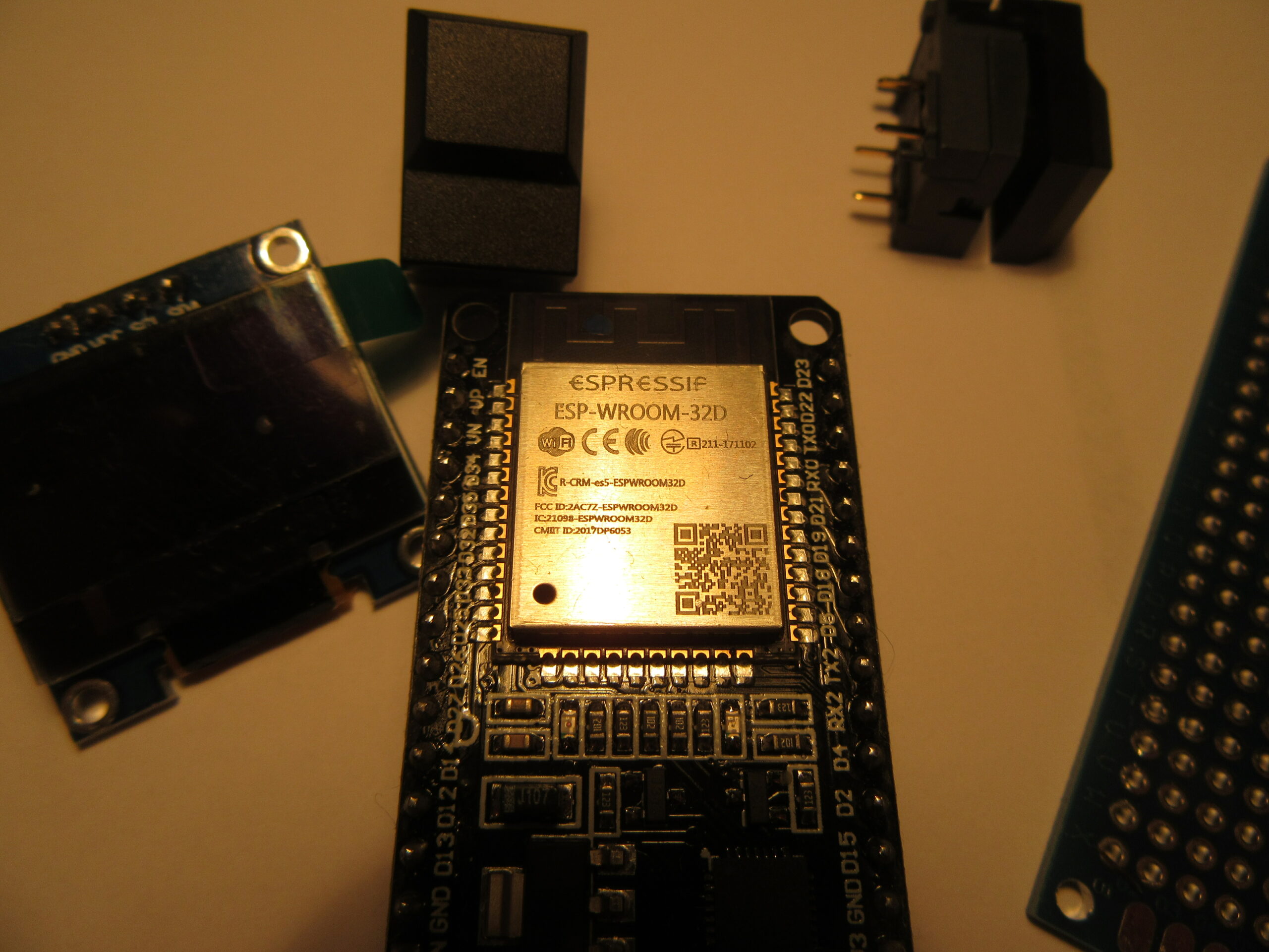
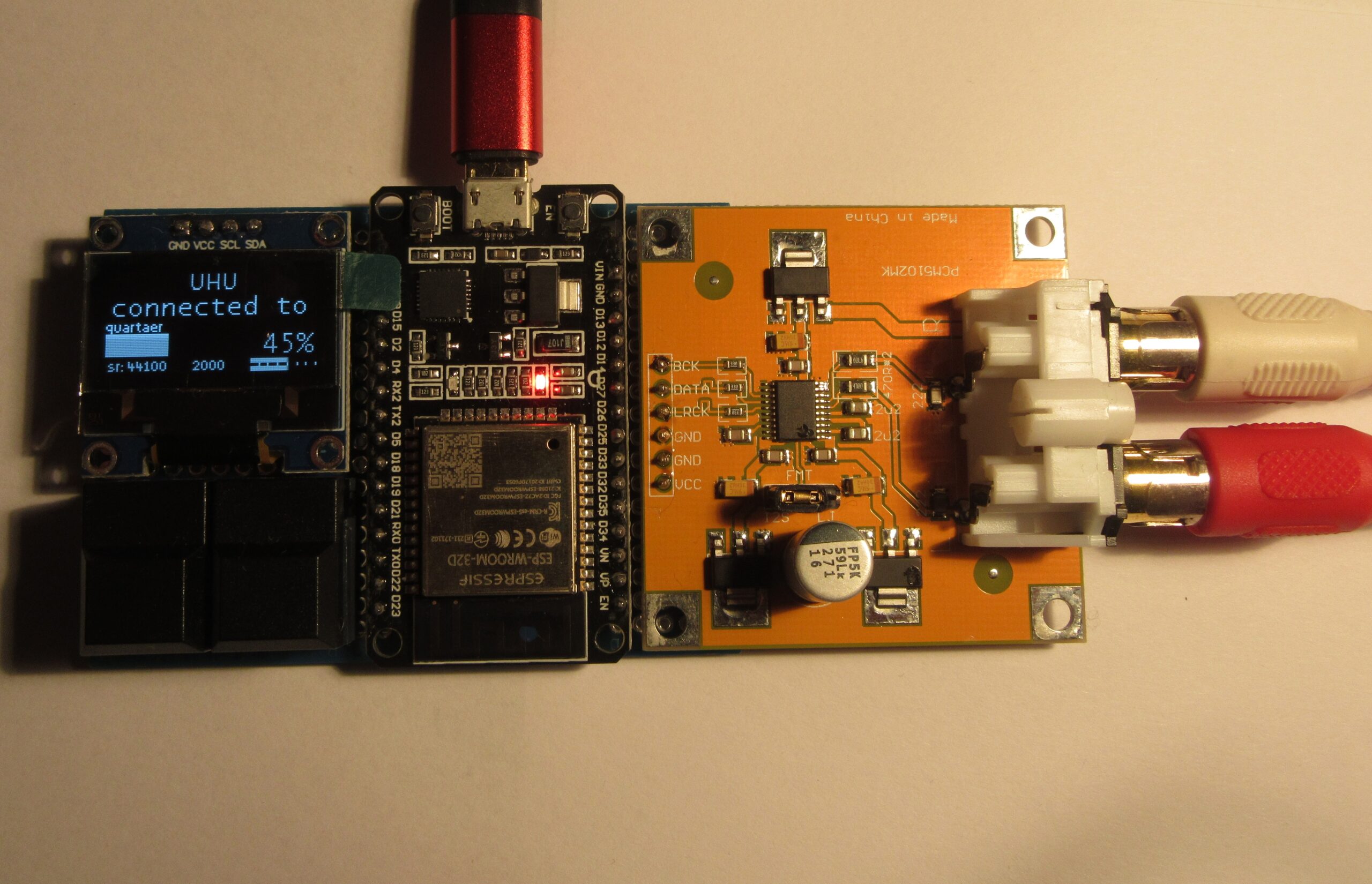
The heart of the circuit is an ESP32 microcontroller from Espressif. The system not only offers plenty of computing power for 3.50 euros, but is also energy-saving. There are a lot of code examples from the manufacturer and lively discussions in forums, which make application development and troubleshooting easier.

ESP-WROOM-32D Modul
ESP-WROOM-32D module

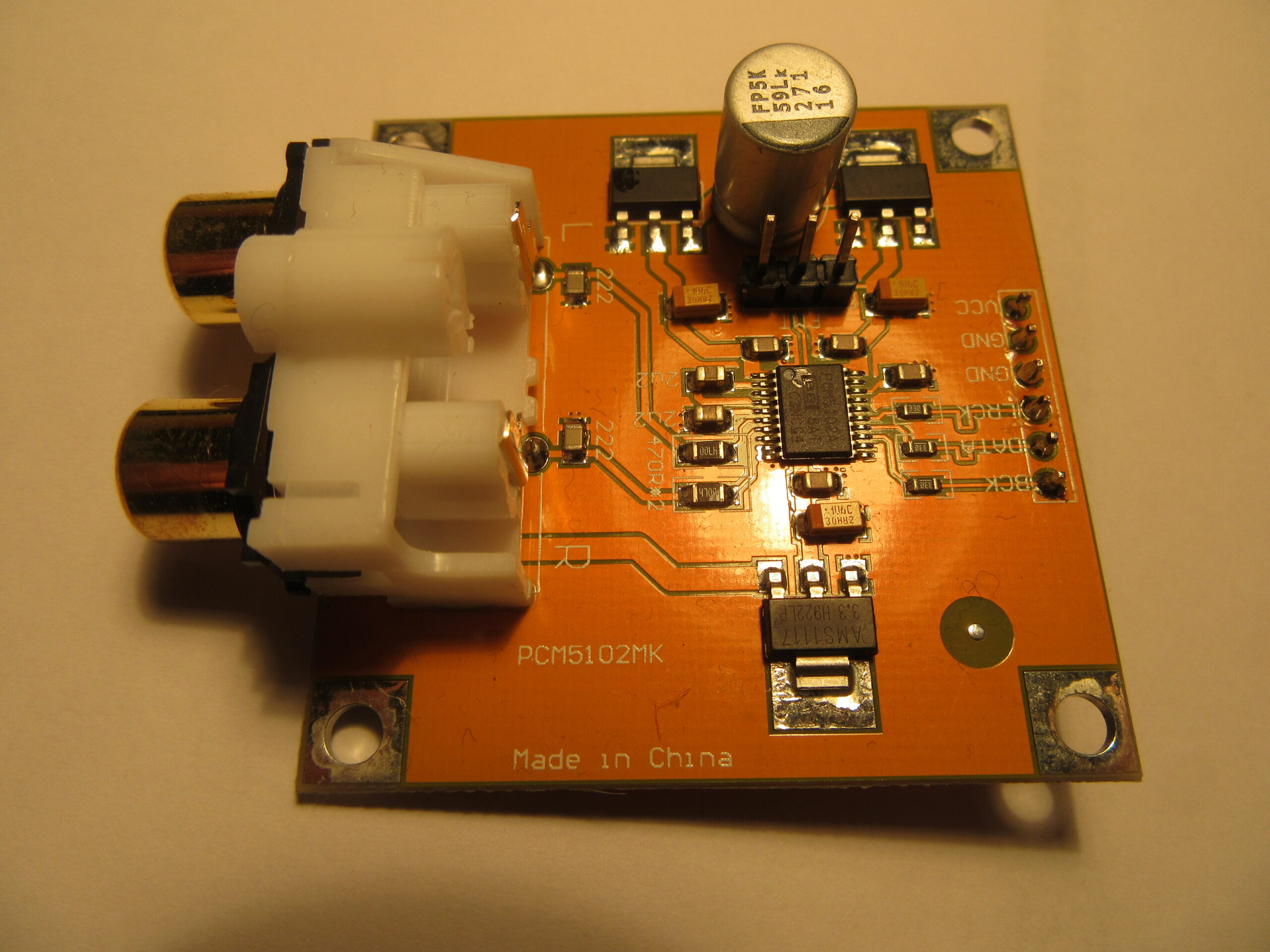
A PCM5102A from Texas Instruments with 32 bit and 112dB signal-to-noise ratio is used as a high-quality D/A converter. It’s actually way too good for Bluetooth audio, but the advantages of 32-bit pay off when it comes to volume control.

D/A-Wandler Board
D/A converter board

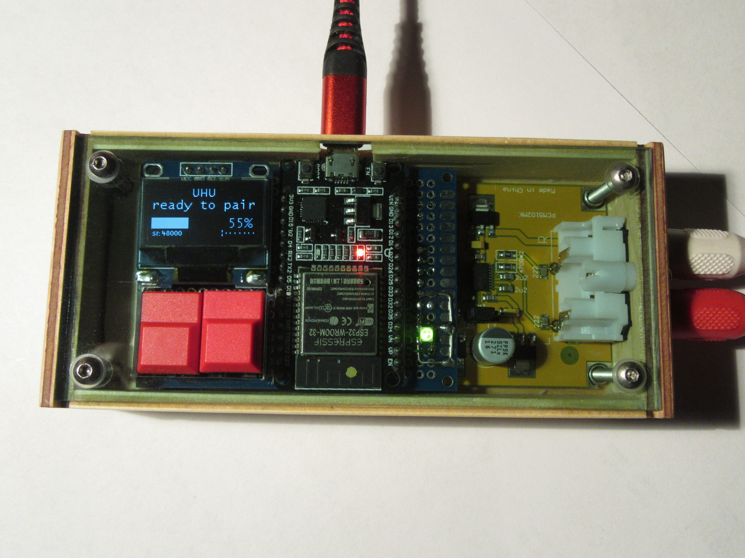
The whole is complemented by two buttons for volume and reset, a 128×64 pixel OLED display and a breadboard. For this project, I use ready-made modules that only need to be connected to each other. This is of course much faster than drafting your own circuit board.
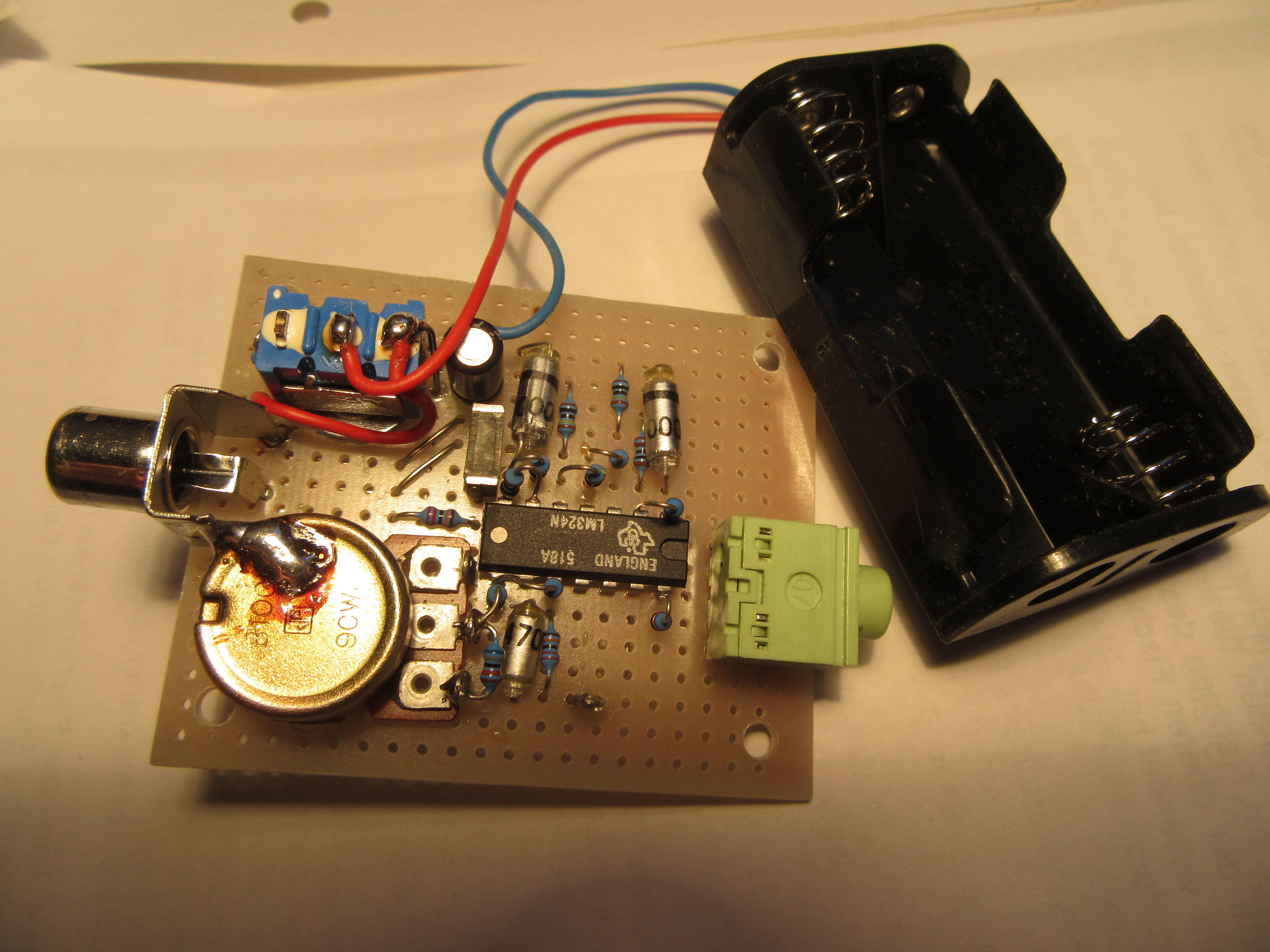
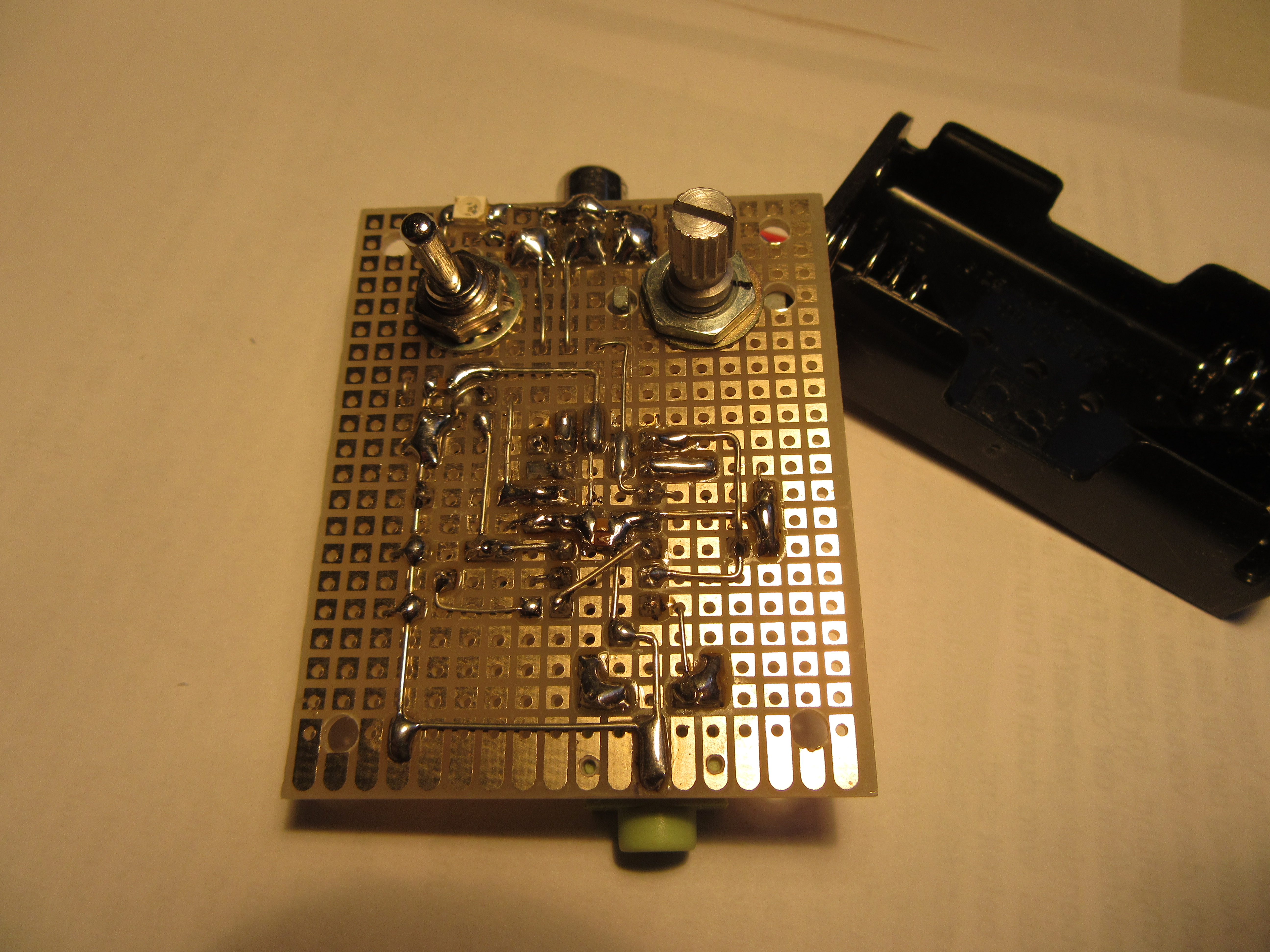
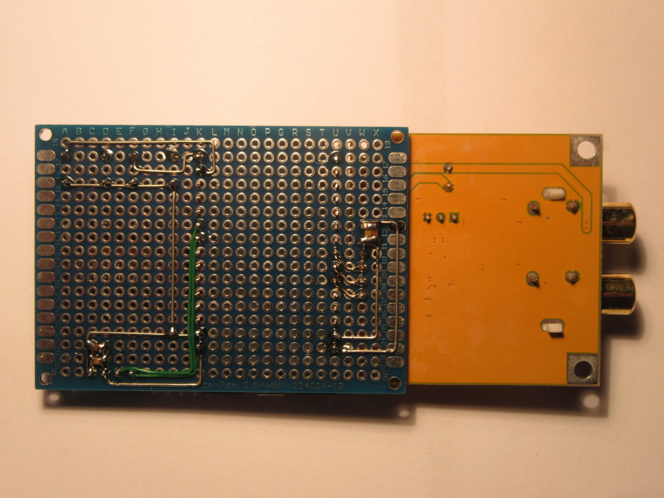
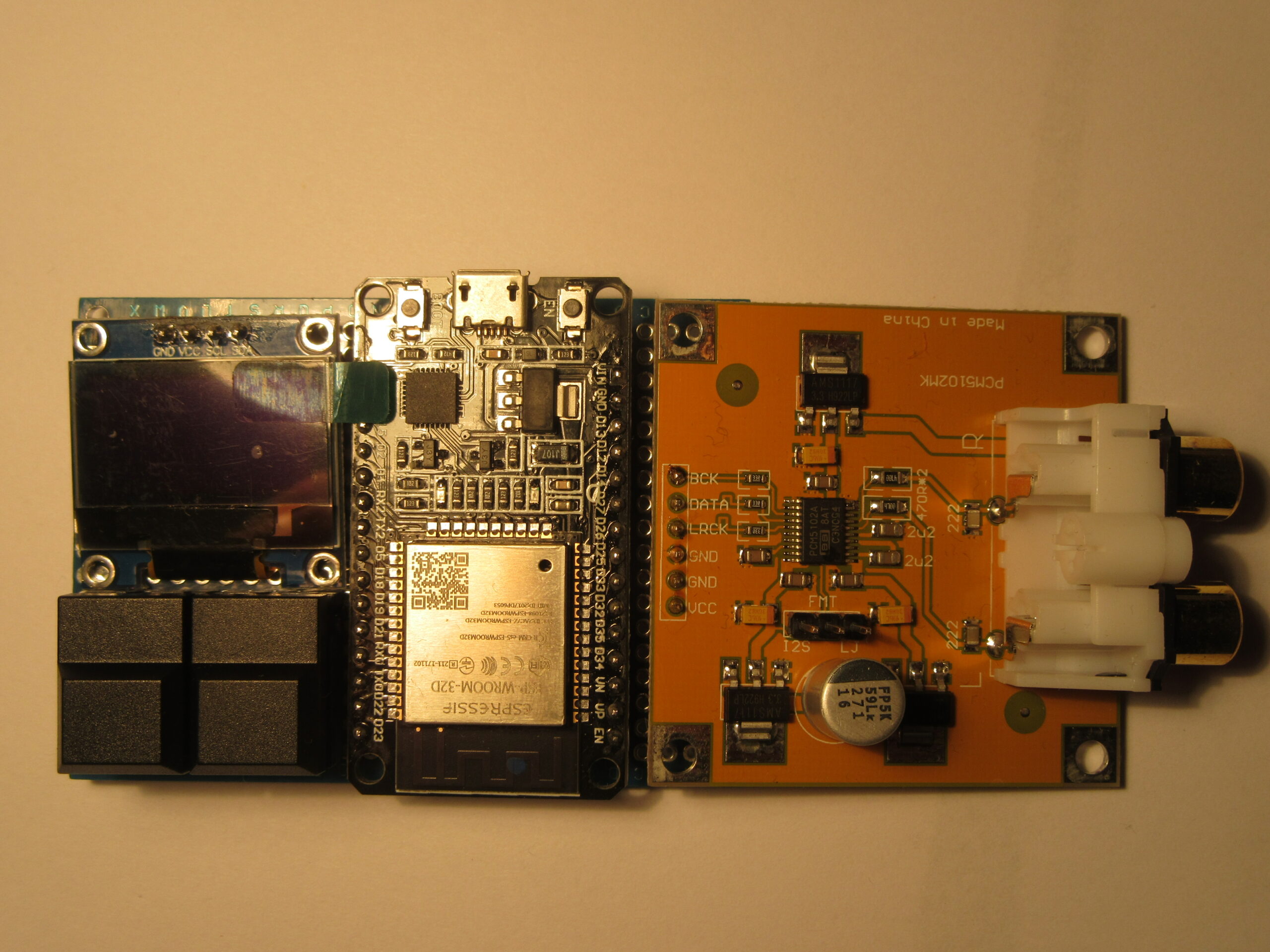
Bauteile
components

Circuit

Since I used finished modules for the project, the circuit is limited to a few connections between the central ESP32 module and the OLED display, the D/A converter and the two buttons. The whole thing is soldered together in an hour.

Verdrahtung Unterseite
wiring bottom
Schaltbild
schematics

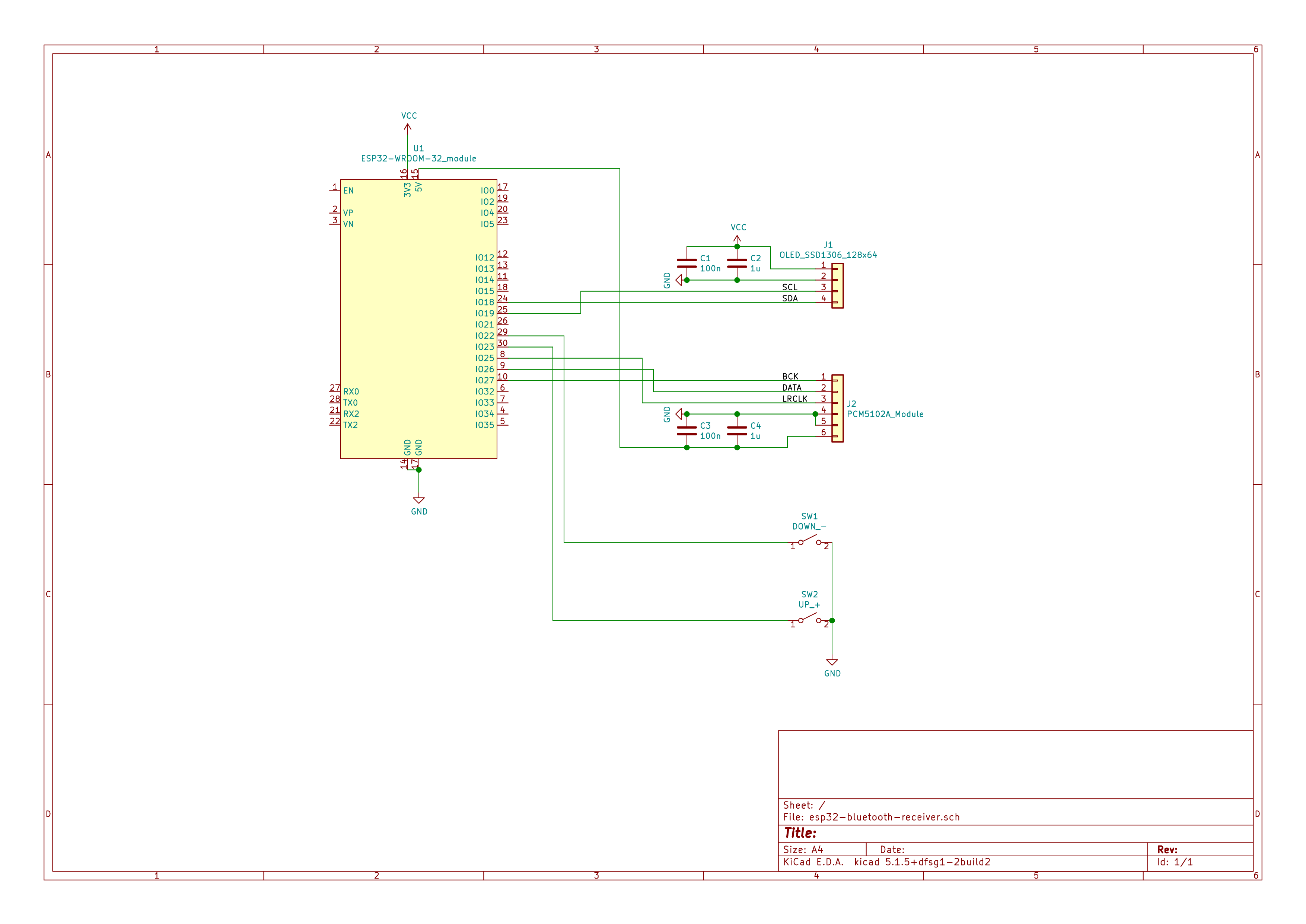
The circuit diagram is available here as a pdf.
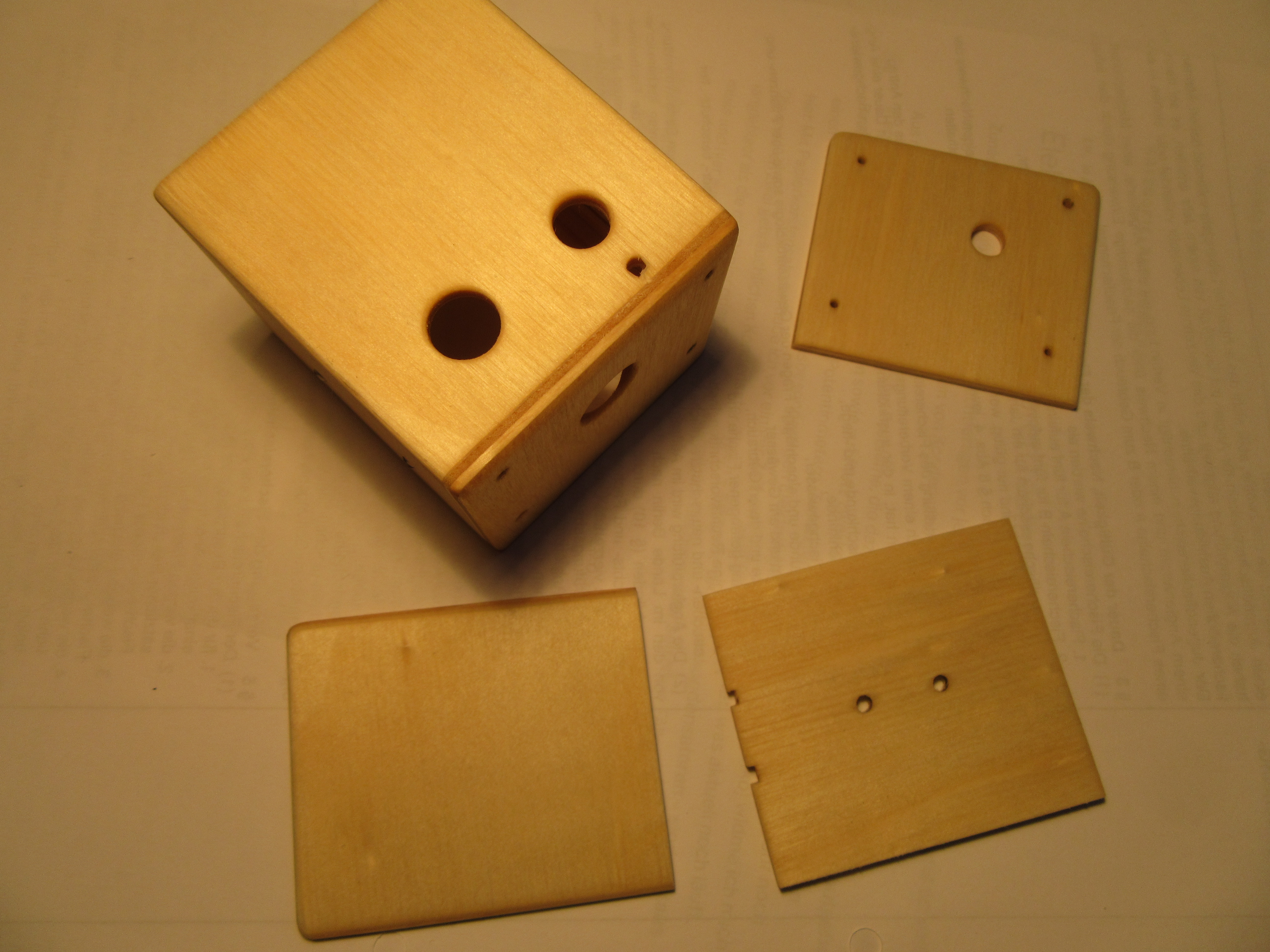
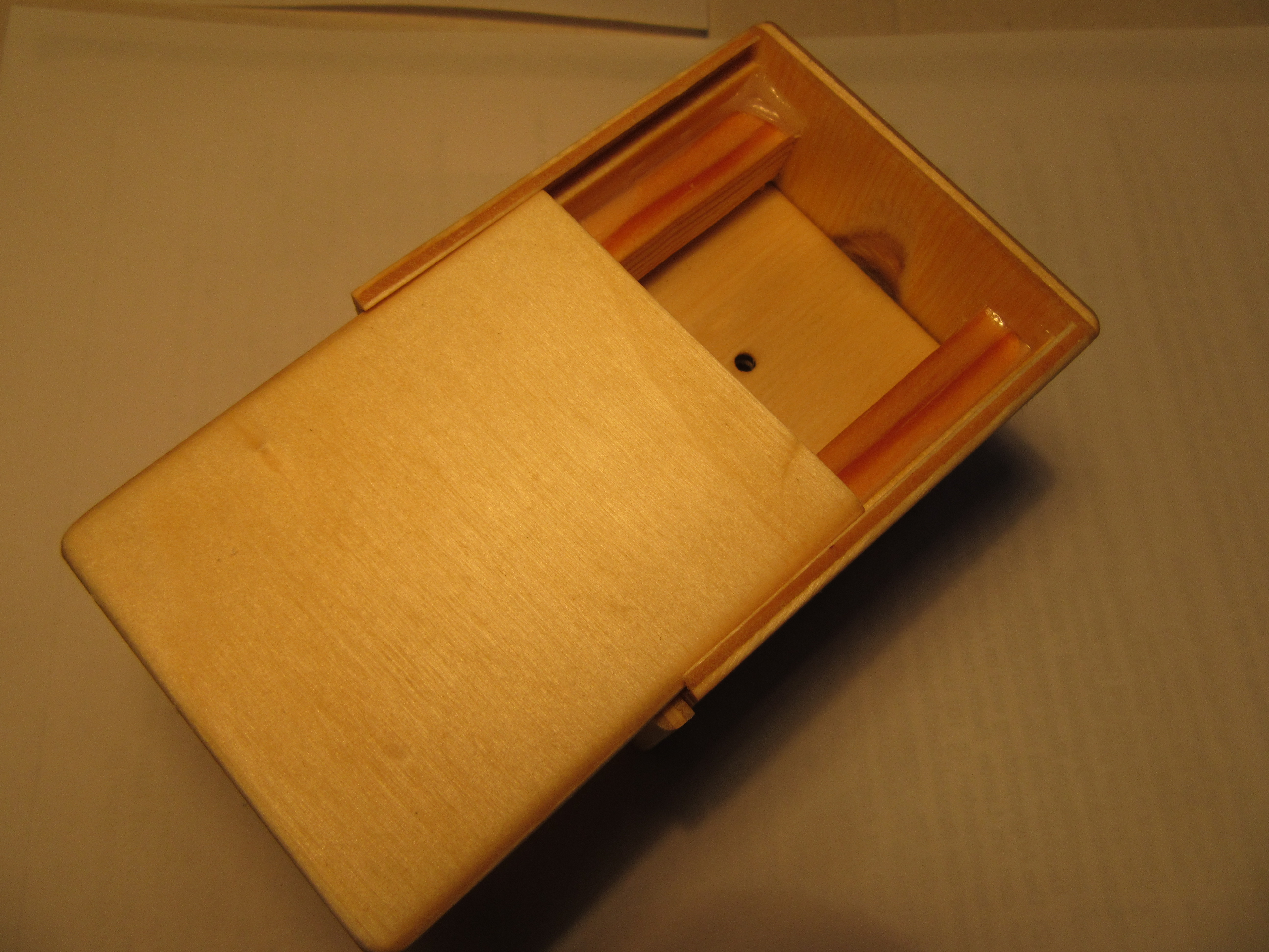
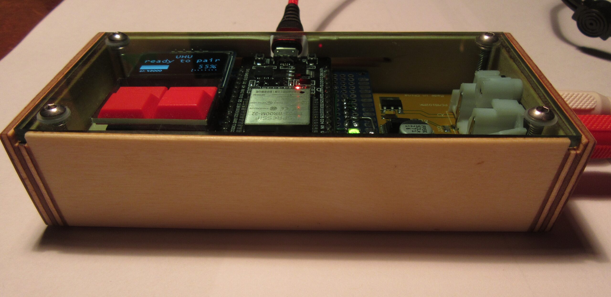
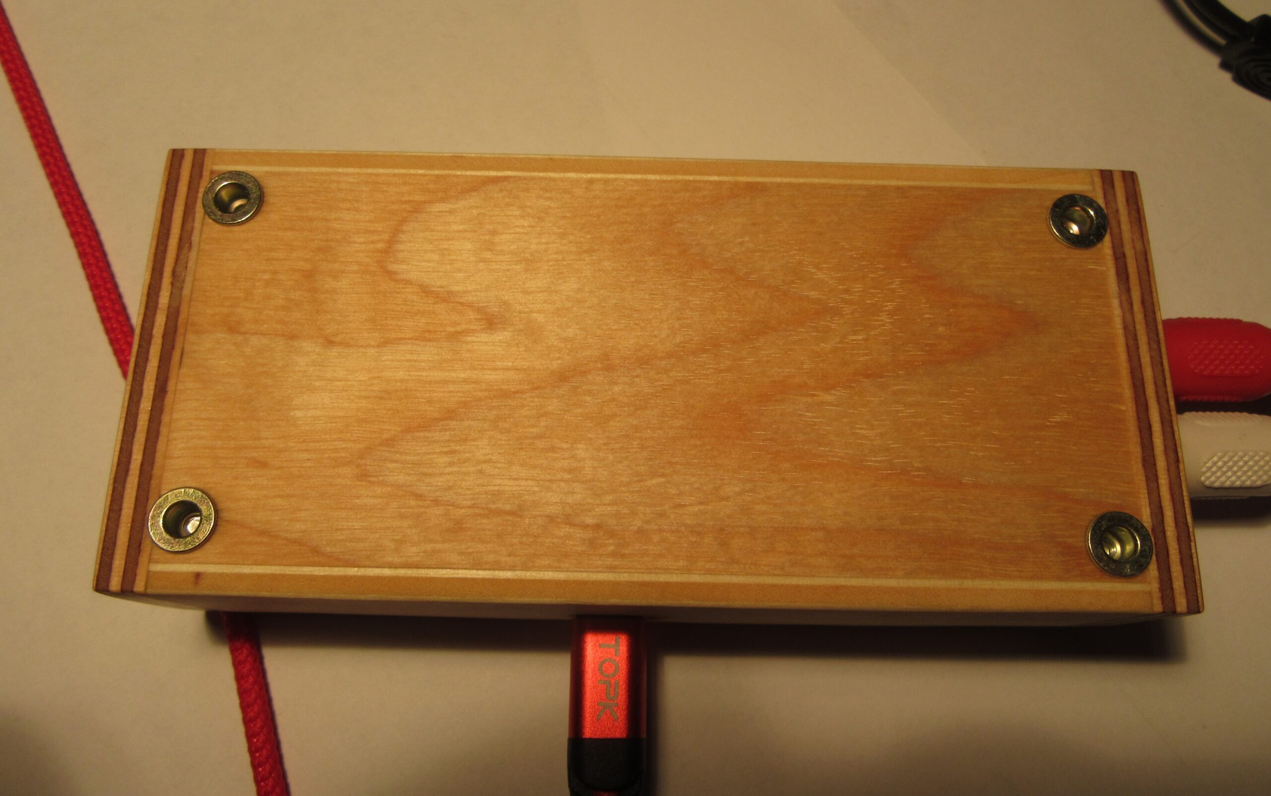
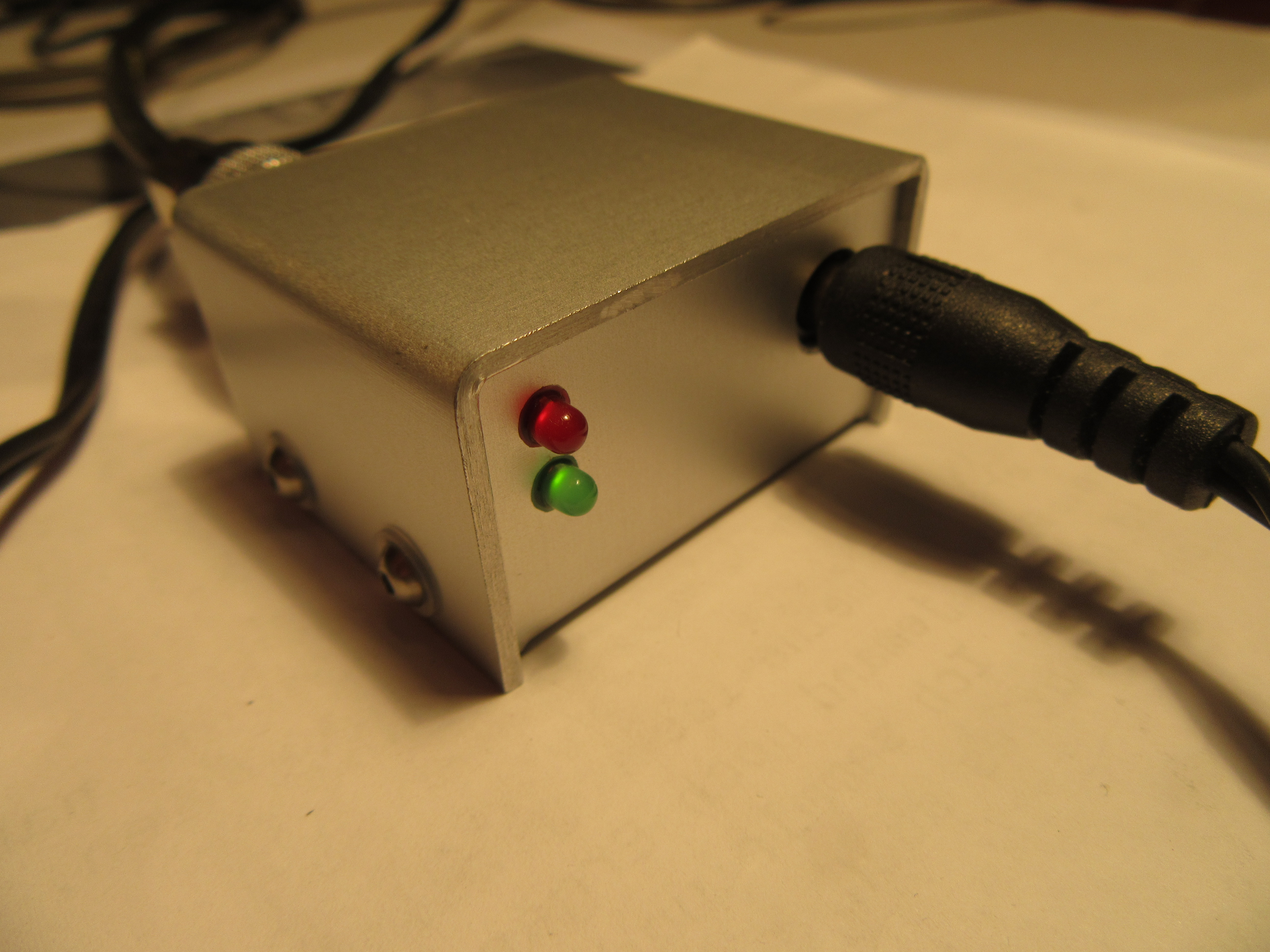
Prototyp
prototype
Funktionstest
function test

Case

I built a small housing from glued plywood scraps, which has become very chic and goes well with the Sony receiver for my taste.

Gehäuse aus Sperrholz - Vorderseite

Gehäuse aus Sperrholz - Unterseite
case made of plywood, front and bottom

Software

The software is derived from the example “A2DP-SINK” from the ESP32 manufacturer Espressif. That shortened the development time a lot for me, as the complete and rather complex Bluetooth communication is already implemented in the example. I added processing of the audio samples for volume control and the conversion from 16 to 32 bits as described above. I also added the routines for the OLED display. The operating status, the connected device and a logarithmic level display are shown on the display.

In the end, the programming and troubleshooting took a lot longer than a weekend, as a lot of bugs had to be found and fixed.

I have published the full source code, the instruction manual and guidance for compiling the project on Github.

https://github.com/uhucrew/bt-receiver-pcm5102a


Receive updates directly in your inbox

Loading

Weekend projekt: avalanche pulse generator

This project I started on a leisure weekend some time ago. The time is now to document it. Always wanted to measure the bandwidth of my two oscilloscopes, an analog and a digital one. There is help from the avalanche breakdown. During this type of breakdown, free carriers in the p-n transition region are exponential multiplied, leading to a rapid current rise. In other words, you can generate pulses with a very short rise time.

Idea

The idea I got from this article: Avalanche Pulse Generator Build Using 2N3904. The circuit is very simple but needs at least 120V to operate. Blessedly is no exotic component included like an avalanche-diode. Many standard transistors you may have in your junk box can be used for the avalanche breakdown. I found some 2N3904. Suddenly cutted a piece of breadboard, collected the remaining components and heated the soldering iron.

components and breadboard

Circuit

A old-school 555 timer IC acts as high voltage generator, a circuit I used several times before, for instance in the VU-Meter with EM84. The avalanche pulse generator itself is composed of only six components as you can see in the schematics diagram.

Schaltbild
schematics

Construction

Initially I tried with the 2N3904. My transistor batch purchased from SEGOR-electronics GmbH Berlin had an avalanche breakdown at 130V. At this shop I purchased some 2N2369A too which had the breakdown at about 90V. For this project the 2N2369A is a better choice and I like the vintage TO18 metal case. Depending on manufacturer and production date I suspect a large variance in the avalanche breakdown voltage of different transistor lots. So you have to experiment a bit to find a good matching part.

put together

Shortly the small circuit was assembled and operated at the first go. Excitedly I awaited now the bandwidth check of the oscilloscopes. There is no formula definition to calculate bandwith from rise time. Usually the bandwidth is calculated with 0,35 divided by rise time. The rise time is the time meanwhile the signal grows from 10% to 90% of the maximum.

Oscilloscope tests

First in turn was the good old analog Tektronix 2465B. (1991 model)

bandwidth test TDS2465B

The screen has markers at 10% and 90% and a cursor for Δt which makes it easy to adjust the trace and read out the rise time. The determined 0.78ns rise time is equal to a bandwidth of about 450MHz. This is distinctly more than Tektronix guarantees, I’m satisfied.

Next in turn was the digital TDS784C. (1996 model)

TDS784C rise time

The device can measure the rise time automatically. The result is fairly exact 1GHz bandwidth, as the manufacturer says. Interesting for me was the fact that the signal rise stopped at about 10% for some time and grows very fast later as you can see better with a zoomed x-axis.

rise time detail

Case

Summa summarum all went as expected and I learned some things. In the end the circuit got a cute case at this time labelled indeed.

Receive updates directly in your inbox

Loading

Weekend project: bat detector

Since ages I observe lots of bats in the evening and I’m interested in there specific style of orientation and communication. Two weeks ago I had some leisure time to build my own bat detector.

I wanted to build a prototype on a stripboard only and investigated to find a premade circuit. A short internet enquiry showed up a bunch of instructions. After some reading and checking my stock of components I decided to go for a simple analog circuit built around one 4xOPV LM324N.

block diagram

The principle is similar to a superheterodyne receiver. The high frequency input is amplified by about 140.000x and mixed with an oscillator signal to an audible frequency range. The concept of a frequency mixer is comprehensive described at Wikipedia. I implemented only a few modifications in the circuit. So I replaced the 62kΩ resistor in amplifier stage two with an 68kΩ type which increased amplification marginally. Additionally I used a 100kΩ potentiometer because I hadn’t a 50kΩ pot available. The entire circuit without the modifications is available here:


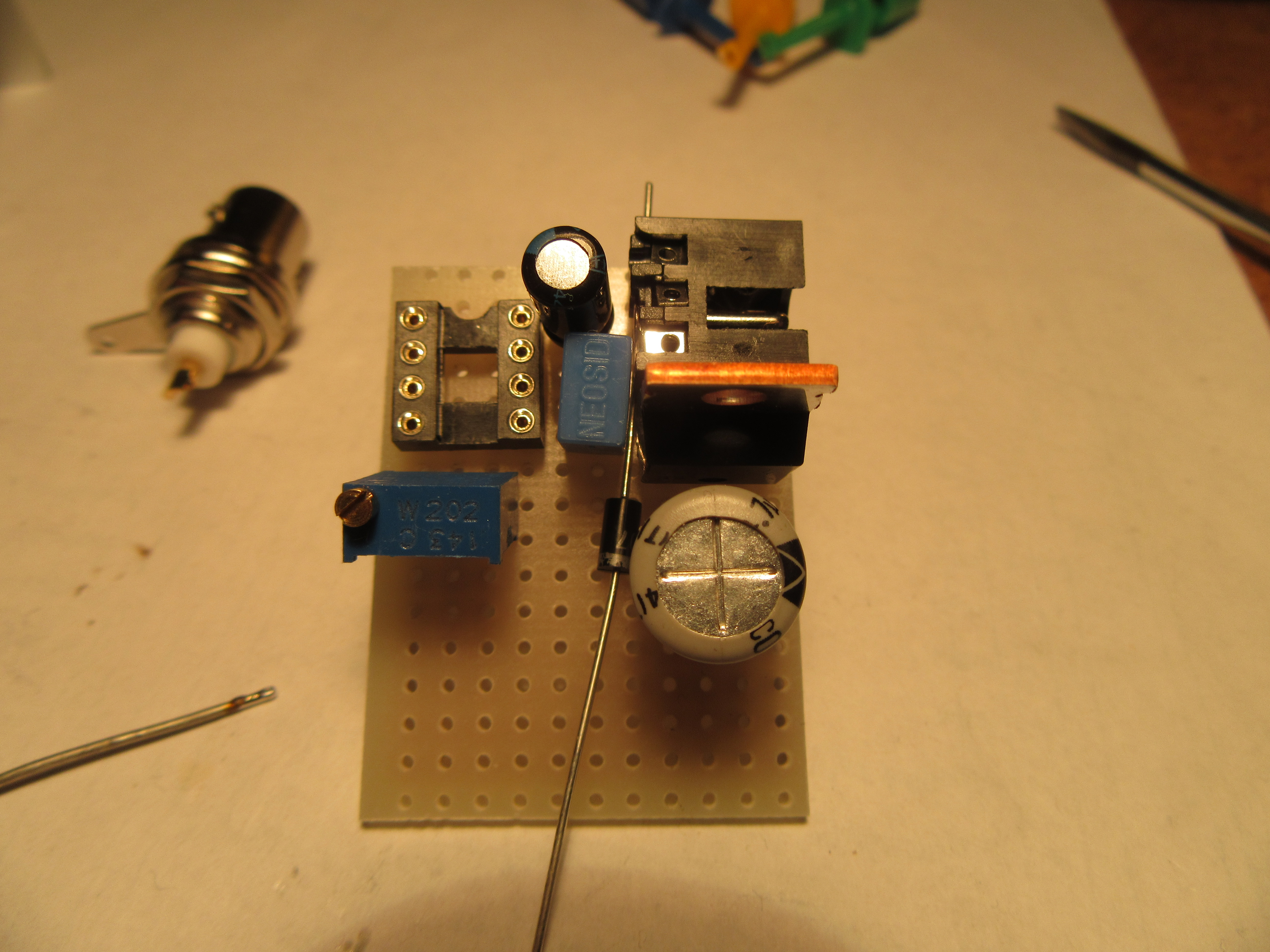
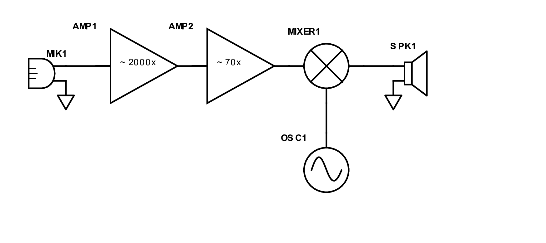
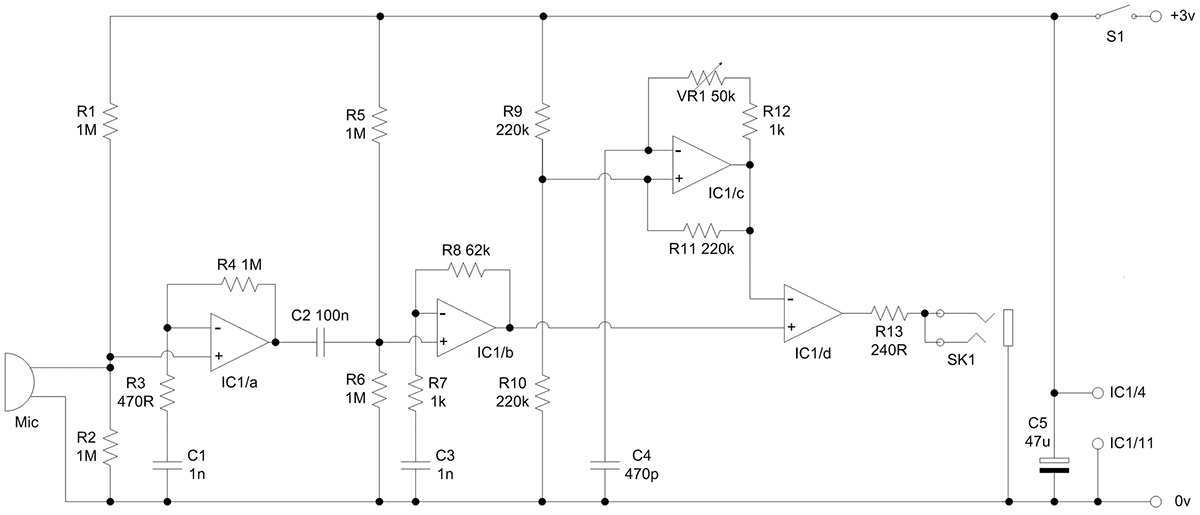
Bat Detector, Source: https://www.nutsvolts.com/

The abovementioned page marvellous describes some background information about bats and the detector which are essential. To use the detector right it’s needful to read the article.

Hereafter is a small picture story that shows the construction. Because I liked the project I designed an adequate chic case from plywood. The microphone is pluggable to allow experiments with different devices.

case parts, gummed up and oil treated
assembly done
stripboard top view
stripboard bottom view
battery compartment
ready for service
microphone (piezo buzzer)

The first trials indicated that patience is needed to hear a bat. The noise is soft and it can can only picked up if the mammals heading is towards your position. In a patio in Berlin where five to ten bats circling during dusk you luckily hear every quarter hour a kind of rhythmic giggle.


Receive updates directly in your inbox

Loading