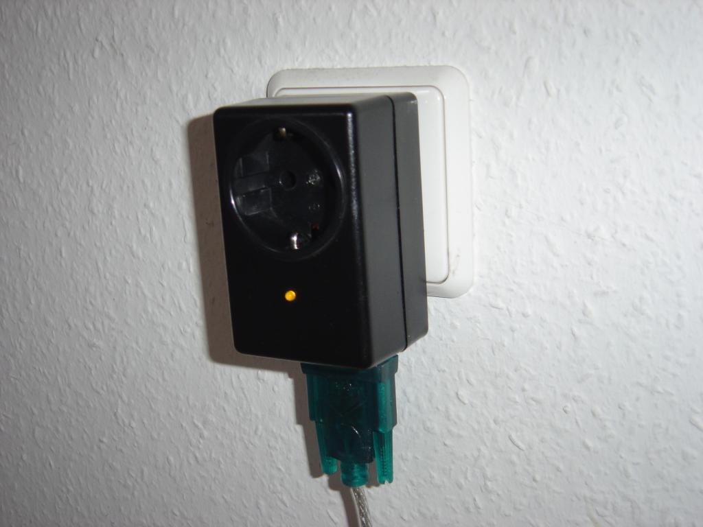
Since some years I’m planning and sometimes working on a project to create my own LTZ1000A programmable precision voltage reference. Up to now I developed most of the circuit and collected the special components like resistors with 0.1 ppm drift per degree temperature change produced exclusively for me. I want to show that it’s possible to create it as a home brew version.
This circuit is operated with mains voltage and some parts are directly connected to line power. So it is only intended as an example for experienced hobbyists.
The circuit uses an Atmel ATTINY2313 controller with well documented firmware written completely in AVR assembler. Beside the dim and switch once functions flexible timers can be used to switch on and off in a cycle, once or repeated. However after power loss all timers are reset and have to be reprogrammed. More details you can find in the serial protocol description.
With the ATTINY2313 builtin analog comparator the zero crossing of the mains AC is detected to fire the Triac at the right time.
The source code is provided under the GNU General Public License (GPL) and can be downloaded here. An already assembled version in hex format is here available.
project goals
simple, clear text commands can be invoked from a terminal
cheap parts, neither transformer nor RS232 isolation IC used
intelligent autonomous cyclic and single switching functions
The schematics is provided under the GNU General Public License (GPL) and can be downloaded here.
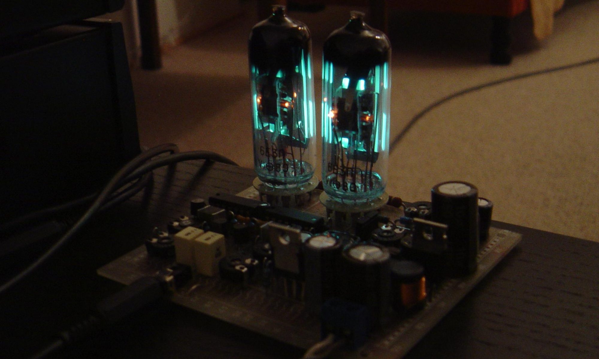
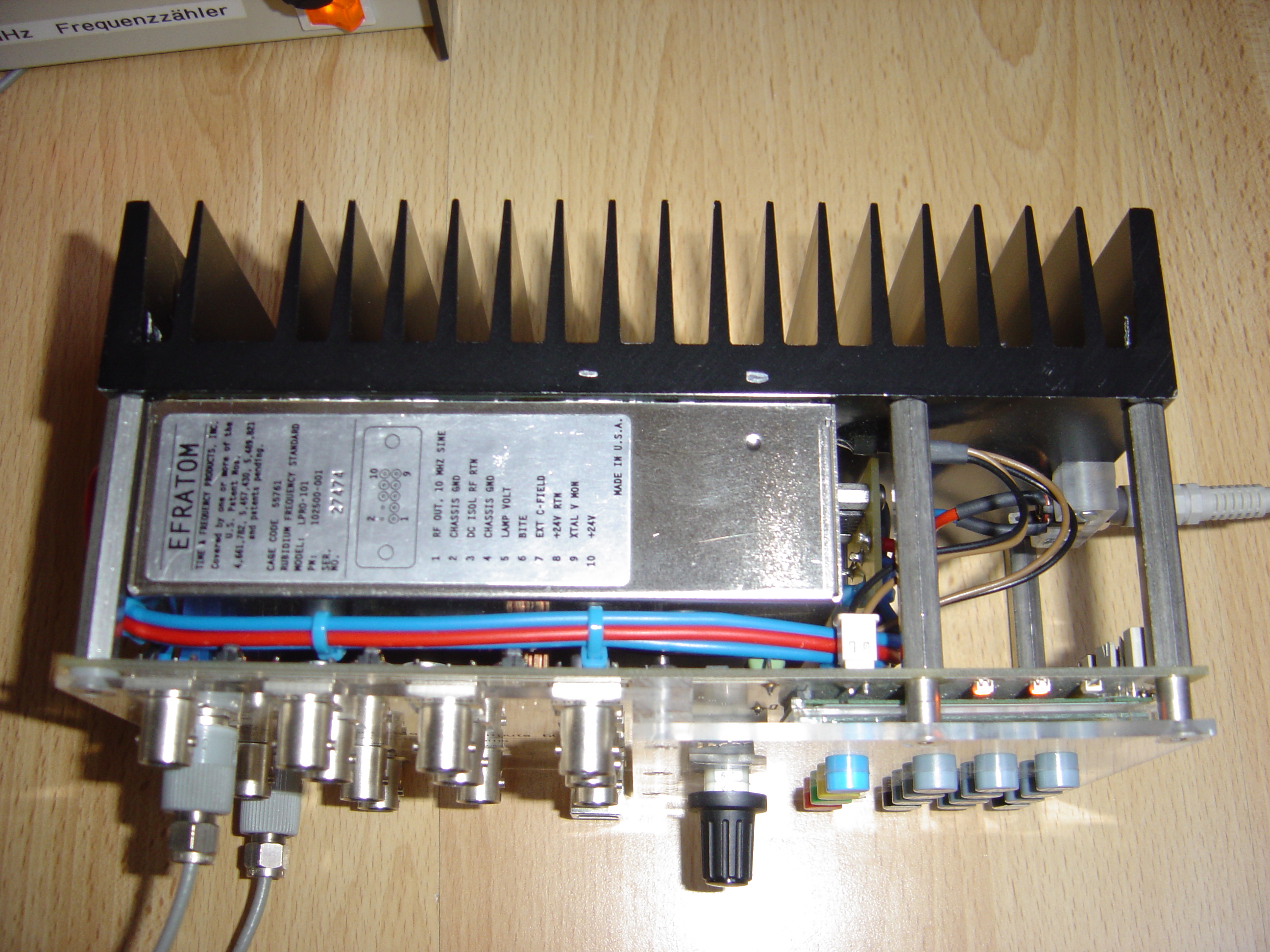
In 2009 a seller from China appeared on ebay.com and offered a large stock of used, about 10 years old “Efratom LPRO-101 Rubidium time base” for a very reasonable price of about 40 US$. In a laboratory you should have an exact time base and I didn’t own one before, so I ordered it. Once arrived I started to create some electronics around the LPRO-101 module with the aim to build a high quality device that feeds other laboratory appliances with an exact clock.
foto of the prototype
This project uses a 10MHz rubidium atomic clock as the time base. Several 10MHz reference outputs are provided at different levels for my other workbench equipment. An integrated Cypress CY22150 CyberClock PLL uses this reference to make 6 PLL outputs with 2.5V and 3.3V level available. The PLL can be programmed with the integrated microcontroller Atmel ATMEGA644.
An USB-port is present to program the PLL alternative with the software from the project “CyberClock CY22150 with USB and control software”. For the USB to I2C interface I used also here the “I2C-Tiny-USB” adapter, developed by Till Harbaum with drivers available for Linux, Windows and MacOS. At the I2C-Tiny-USB homepage you will find the firmware for the ATTINY45 controller.
The device contains a keypad with four hotkeys and a rotary encoder for menu driven user input. A LCD-display shows the actual output frequencies and device status. Case and heatsink temperatures of the LPRO-101 are monitored with 1-Wire temperature sensors. Three LEDs displays the state of the device and signals errors and warnings.
All device states are shadowed in an FRAM RAMTRON FM24CL04. The last state is automatically restored at power up. A maximum of 8 different setups can be saved and recalled.
The firmware for the integrated microcontroller ATMEGA644 is available for avr-gcc. It is written in C and developed with “AVR Studio 4.15”, an IDE for 8-bit AVR-controller by Atmel. The source code is provided under the GNU General Public License (GPL) and can be downloaded here.
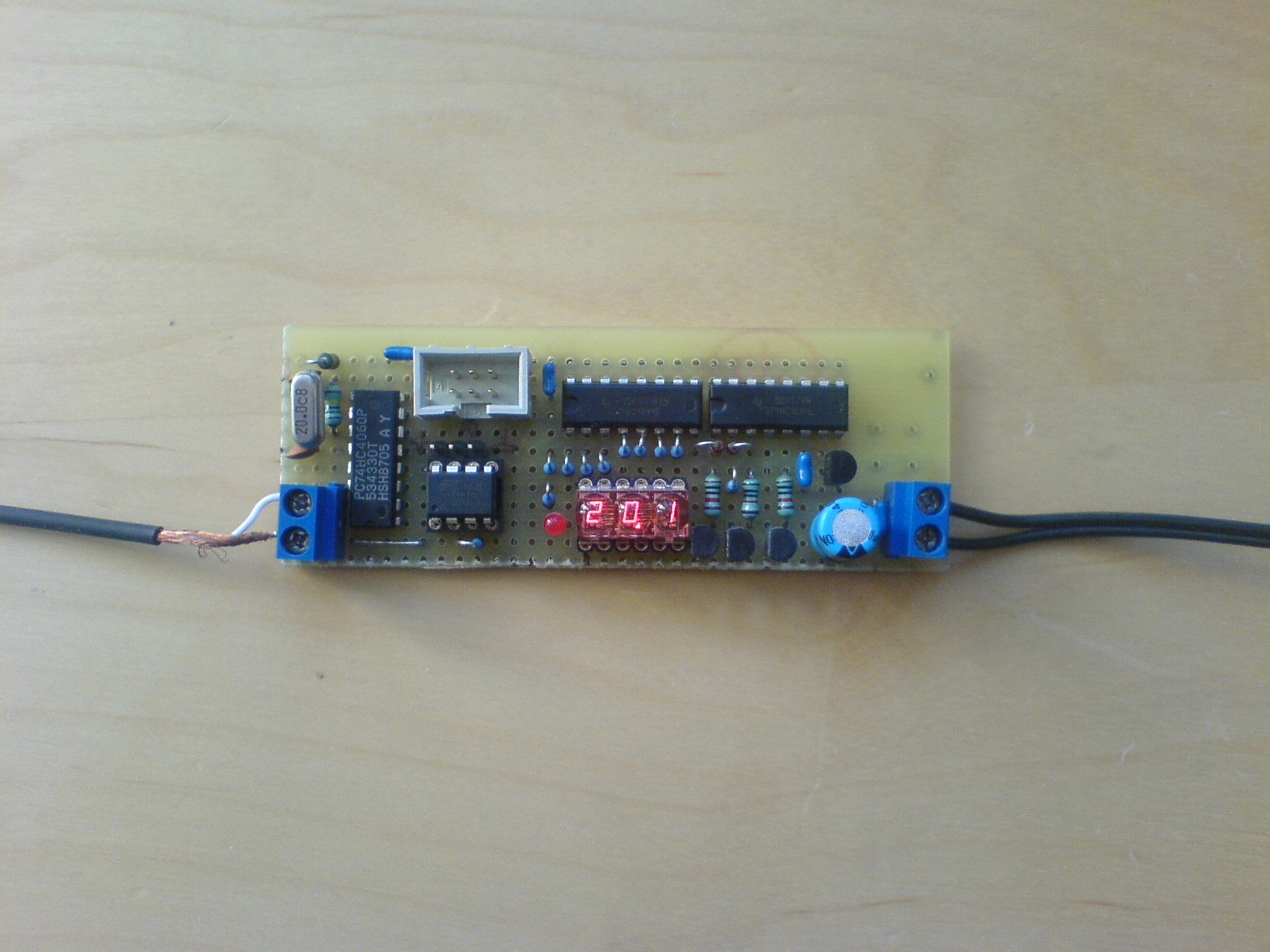
This project demonstrates a complete 1-Wire slave implementation to connect a 1-Wire temperature sensor with local display to the 1-Wire bus.
foto of the prototype
The central part of this circuit is an ATTINY45 controller. The controller is both 1-Wire slave and master. At the master side is a DS18B20 1-Wire thermometer connected. A DS18S20 may be used as well. At the slave side the controller acts exactly as the connected DS18B20. There are two shift registers connected to the controller to drive a 3 or 4 digit multiplex display. The actual firmware drives three digits but can simply adjusted for one digit more.
The ATTINY45 does temperature conversion in a loop and displays the actual value at the local display. For the sensor parasite power is used, so a conversion takes little less than one second. But on the 1-Wire slave side the ATTINY45 delivers immediately the last conversion result. No wait for conversion is needed.
As surplus the internal 2048 bits EEPROM of the ATTINY45 can be accessed from 1-Wire bus with the standard commands for iButtons. It may be used to store minimum and maximum or mean values.
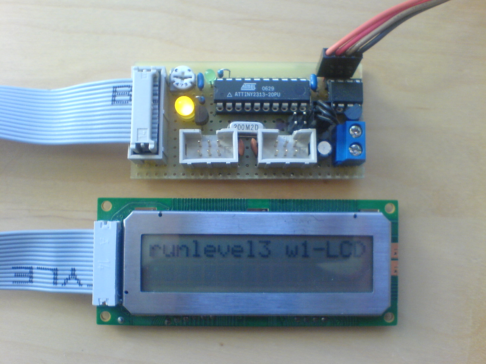
This project demonstrates a complete 1-Wire slave implementation to connect an alphanumeric LCD-Display to the 1-Wire bus.
foto of the prototype
The project consists of two parts:
1-Wire slave, an ATTINY45 controller
LCD-Controller, an ATTINY2313
These two parts communicate over a bidirectional serial connection at 115200 Baud.
Part 1: 1-Wire slave
The 1-Wire slave is software implemented with an Atmel ATTINY45 controller. A DS2401 “silicon serial number” is used to obtain a unique id for the bus without modifying the firmware. The timing should meet the specification, but is not 100% tested. The serial port is also implemented in software. At power up there will be some debug information transmitted. In the LCD 1-Wire protocol description are the 1-Wire commands described to control the LCD-Display. All command and data is integrity protected by crc16.
Additionally as surplus the internal 2048 bits EEPROM of the ATTINY45 can be accessed from 1-Wire bus with the standard commands for iButtons.
The source code is available here.
Part 2: serial LCD-Display
This project part connects a HD44780 compatible LCD-Display to a serial port. In the LCD serial protocol description are the serial commands described to control the LCD-Display. All command and data is integrity protected by crc16. This project part may be used stand alone, without the 1-Wire interface from part 1.
For switching and dimming of a backlight is a PWM output available. The PWM is set with an 8 bit value and is automatically smooth adjusted.