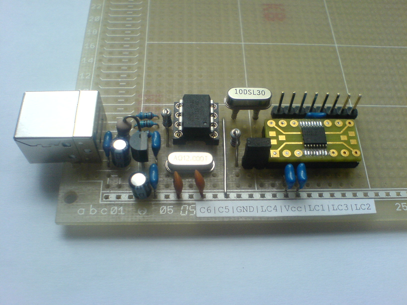
This project connects the I2C-interface of a Cypress CY22150 CyberClock to an USB-port, a control software with graphical user interface is provided to program the CyberClock.
For the I2C-interface I used an “I2C-Tiny-USB“, developed by Till Harbaum with drivers available for Linux, Windows and MacOS.
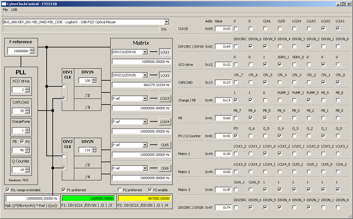
The control software “CyberClockControl” is available for Linux and Windows and possibly for MacOS. It is written in C++ and developed with “Qt Creator”, a Cross-Platform Qt IDE by Qt Software. The source code is provided under the GNU General Public License (GPL) and can be downloaded here.
software goals:
- multi platform graphical user interface
- compute two different frequencies with only one PLL in the chip
- better algorithm than the Cypress Software CyberClocks (smaller Q-value)
- real time editing and computing of chip registers
The schematics is available for download here.
CY22150_i2c-tiny-usb_schematics
Program binaries are provided for linux/x86_64 and win32. For win32 you have to install the libusb driver from the source code.
Addendum from 2022-11-6:
I have made a new version of the software available for linux/x86_64 and win32 with the change that the I2C address can now be set differently from the default value 0x69. The reason is that the address of the CY22150 is configurable by software and the default settings are stored in an internal flash memory. Therefore, it is possible that you may come across chips that are configured with a different address. Unfortunately, Cypress keeps the algorithm for programming the flash secret. There is also no information about the possibility of changing the I2C address in the data sheet. From an engineer’s point of view, this withholding of information for a product is simply embarrassing. And perhaps rightly, the Cypress company is now history. It would be easy to figure all this out with reverse engineering, but I lack the ambition. The I2C address is – of course undocumented – in the configuration memory at address 0x11, ORed with 0x80. Here, the I2C address can be changed at any time during runtime. After switching off the operating voltage, however, the address is reset to the standard.
If you really want to change the flash of a CY22150, you need two things:
- A “CY3672-USB” programmer, which is no longer available, and
- the software “CyberClocks”, which is available here for free after registration.
Here you will find information from the manufacturer on flash programming of the ICs.
Hello! I express my gratitude for your project “Cyberclock Cy22150”. I collected “i2c-Tiny-USB”- everything worked, I checked the test with a display 1602. I ask you to help me, I hope it will not be difficult for you. My problem: I came across a CY22150 chip with an address on the 0X6AH bus (instead of 0X69H by default). My request to you: compile for me a program for Windows with address 0x6ah. I am a radio amateur, I have difficulty programming. As I understand it, you need to change in the “i2c_usb.h” file value 0x69 by 0x6a
“// CY22150 Chip Address
#define CY22150_ADDR 0x69 ”
And then get the file “CyberclockControl.exe”
I hope for your help.
By the way, maybe you know how to change the I2C address from 0x6a to 0x69 in the CY22150 chip itself?
This would completely solve my problem with the device where CY22150 is used !!!
Hi Dmitry,
I wrote an addendum at the end of the article and modified the software to change the I2C-Address. Hope that helps.
Best,
Uwe
Hello. Thank you so much for taking the time to help me.
CY22150 began to be determined – to respond to Skan – Open usb !!! (frequency = 3.597Mhz).
But my expectations were not met, CY22150 – does not remember the state of the frequency 3,597 Mhz
after power off.
(does not remember in its EEprom).
So the question arises – should CY22150 remember the frequency value after using CyberClockControl ???
]]]]]]]]]]]]]]]]]]]]]]]]]]]]]]]]]]]]]]]]]]]]]]]]]]]]]]]]]]]]]]]]]]]]]]]]]]]]]]]]]]]
I read the forum on your link and found interesting information.
Here is the quote:
—————————————————
https://community.infineon.com/t5/Clocks/CY22150-Jedec-File-Analysis/m-p/182577
Anonymous
Not applicable
Mar 31, 2012 12:57 PM
CY22150 Jedec File Analysis!
———————————————————–
If you look at the jedec file for CY22150, although the format may not be obvious,
it’s also not complicated. Starting with the first block:
L00064
0101101000000001000000000000000010000100
0000011000001000100010001000000011101100
00110000000000000000000000000000*
In the first line, 64 is the (decimal) bit address of the first bit. Divide this value
by 8 to get the byte address. So this string of bits begins at register address 8.
Divide the bits into groups of 8, representing byte values.
The bits in each byte are ordered MSB to LSB (left to right),
so they are shifted into the I2C port in exactly the order shown.
White space (spaces and carriage returns) are ignored. The above data is shown below as a series of bytes.
I2C
address
08H 01011010
09H 00000001
0AH 00000000
0BH 00000000
0CH 10000100
0DH 00000110
0EH 00001000
0FH 10001000
10H 10000000
11H 11101100
12H 00110000
13H 00000000
14H 00000000
15H 00000000
There is a gap of unused addresses, then the next block of data starts at L00512.
512 / 8 = 64 (decimal) = 40H
Similar breakdown applies for further addresses. So the bits in groups of 8 following “L00512”
in the JEDEC file start at 40h and go to FFh. After L00512 shift in 40h to 47h. Settings after
that do not matter.
]]]]]]]]]]]]]]]]]]]]]]]]]]]]]]]]]]]]]]]]]]]]]]]]]]]]]]]]]]]]]]]]]]]]]]]]]]]]]]
I have written two files to CyClockRT *.Jed with different I2C addresses: 1)69h , 2)6Ah.
and compared.
69h=(0)1101001, and (1)1101001 =E9h
6Ah=(0)1101010, and (1)1101010 =EAh
The changes are present at 11h !!!!!
Only the first bit is different, it always = 1.
Question : is it possible to form a command to write over I2C :
Device with address 6Ah (CY22150), write the value E9h to address 11h. ???
]]]]]]]]]]]]]]]]]]]]]]]]]]]]]]]]]]]]]]]]]]]]]]]]]]]]]]]]]]]]]]]]]]]]]]]]]]]]]]]]]]]]
I tried (for the first time!!) write a sketch
for Arduino to change the device address(CY22150).
Here’s what happened :
——————————–
/*
sketch_CY22150_Change I2C Address
*/
#include
void setup() {
Wire.begin();
Serial.begin(9600);
while (!Serial);
Serial.println(“\CY22150_Change I2C Address”);
}
void loop(){
Wire.beginTransmission(0x6A);
Wire.write(0x11);
Wire.write(0xE9);
Wire.endTransmission();
delay(100);
}
————————————————
The address is changing!!!
But unfortunately, as in your program,
the change is not saved in the EEprom(cy22150).
After removing the power – again 6A….
Maybe try not to write E9h =(1)1101001,
but to write 6Ah=(0)1101010 ???