A small oscilloscope, a Picoscope EO1/7 is in my possession for a long time. When I bought it maybe 20 years ago for nostalgic reasons for little money, I got an extra chassis as a spare parts donor with it. This chassis was rusted, bent, some parts were missing or broken. Of course, there was no tube left either.
During a cleanup this spring, this chassis was supposed to go into the scrap. Before I had the heart to do that, I made an inventory:
- all tubes incl. the picture tube are missing
- selenium rectifier missing
- no front panel and no case
- rust and dirt on all parts
- potentiometer with power switch, mechanics bent, Bakelite switch housing broken
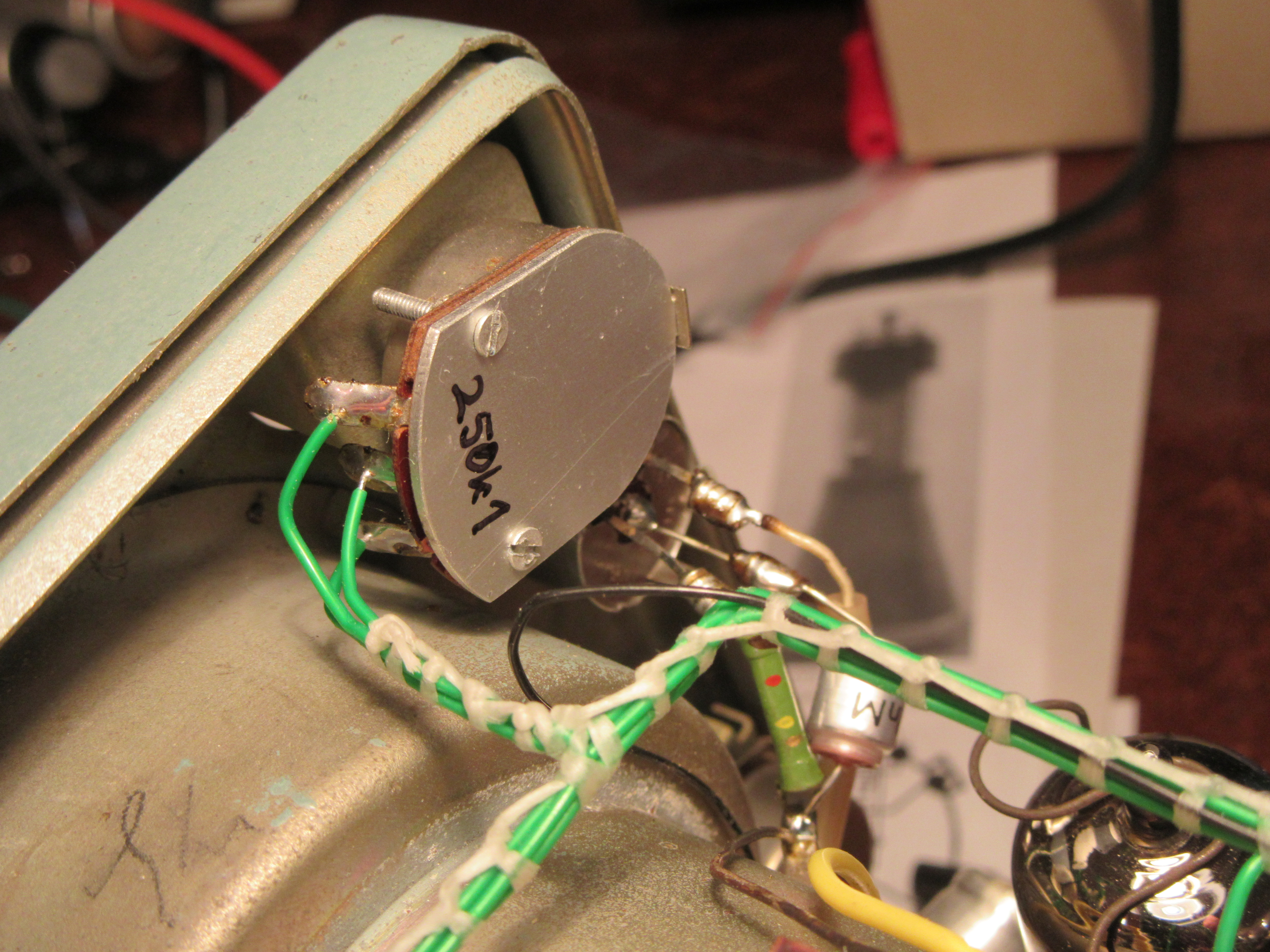
- potentiometer rear cover missing
- fuse holder incomplete
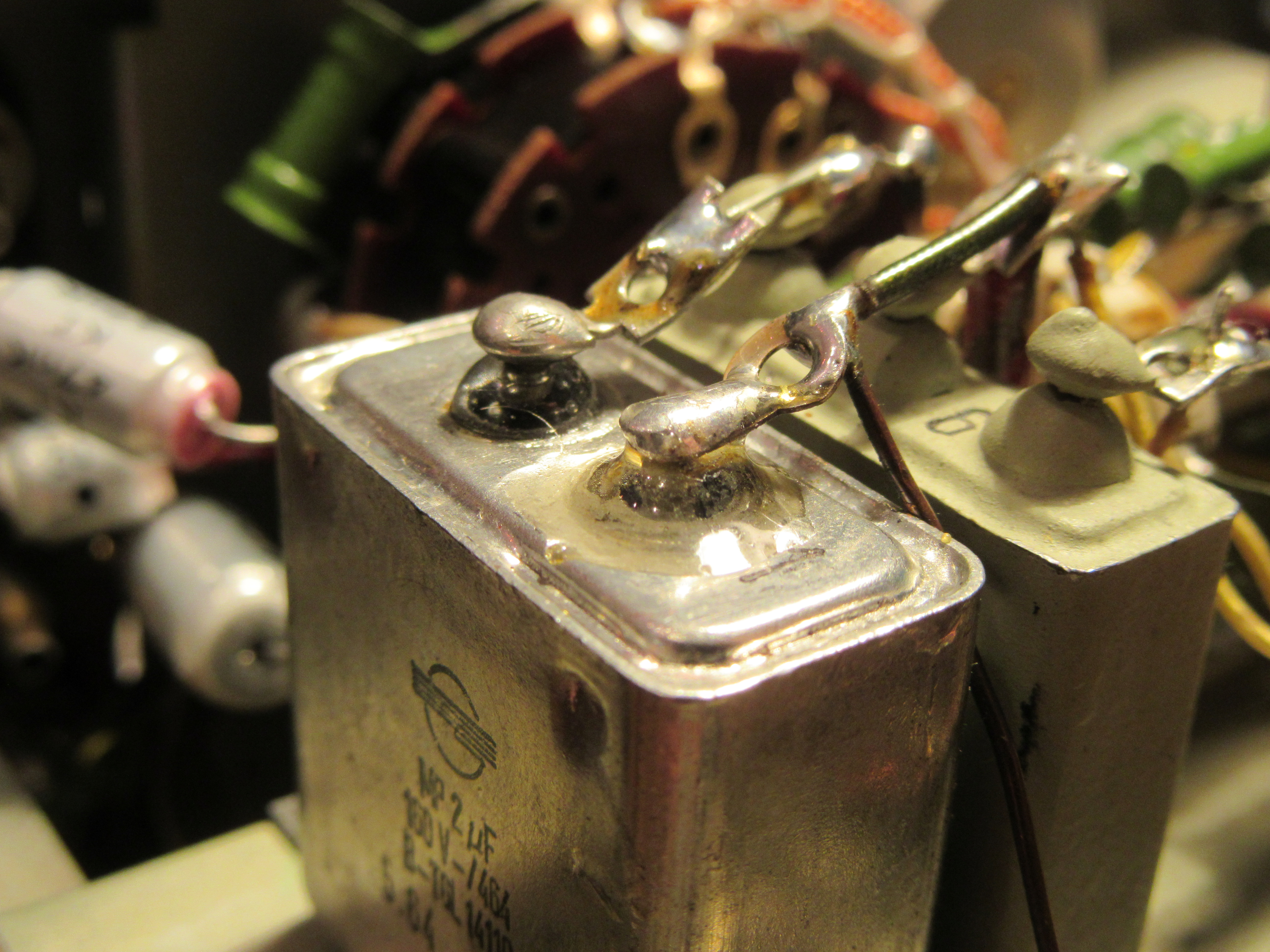
- MP condenser one terminal broken, oil leaking out
- wiring harness partly removed by brute force
- one ceramic tube socket broken
- two resistors destroyed
- few capacitors missing
But the power transformer, the filter choke and a smaller high voltage transformer were apparently still intact. Furthermore, both rotary switches for X and Y were OK. These are quite good conditions for a rebuild I thought. Unfortunately I didn’t take a picture of the original condition. It really looked like a pile of junk.
The beginning
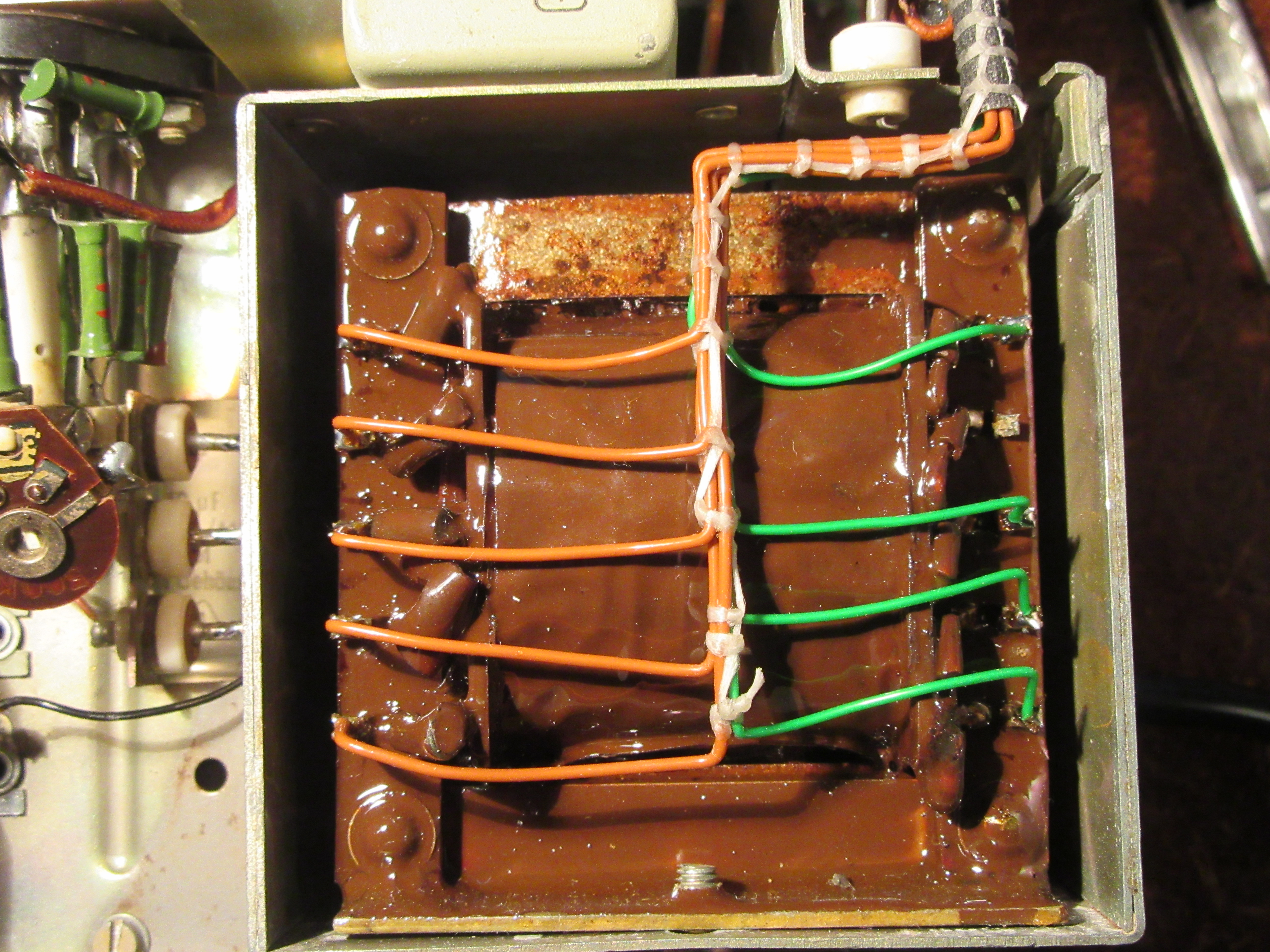
First, I disassembled the unit as much as possible, cleaned it properly and partially derusted it. After derusting, I sealed the power transformer with an alkyd resin lacquer. Basically you should use a high voltage insulating varnish for this. Since this is not so easy to get privately, it does also e.g. a good colorless boat varnish as in my case.
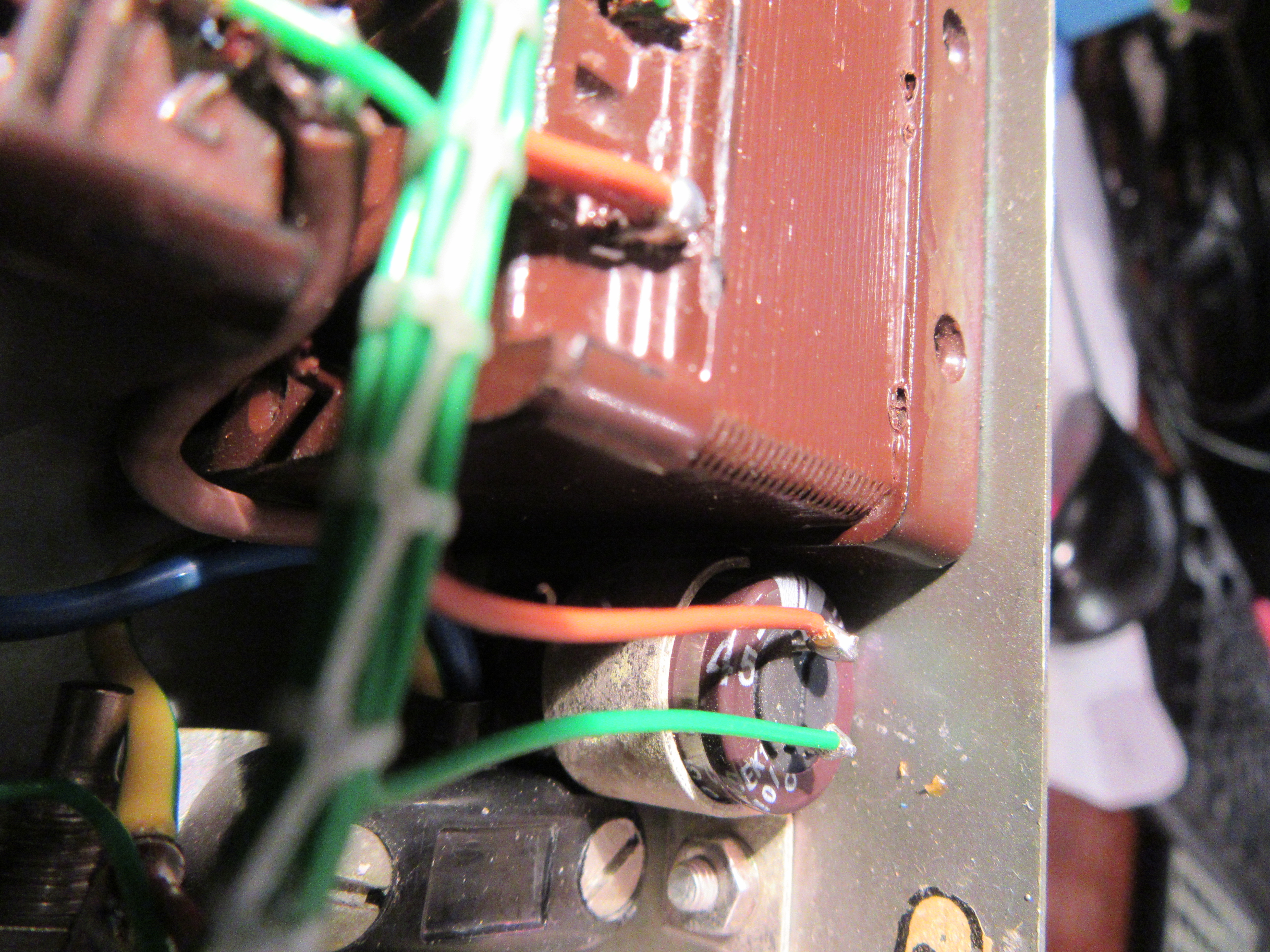
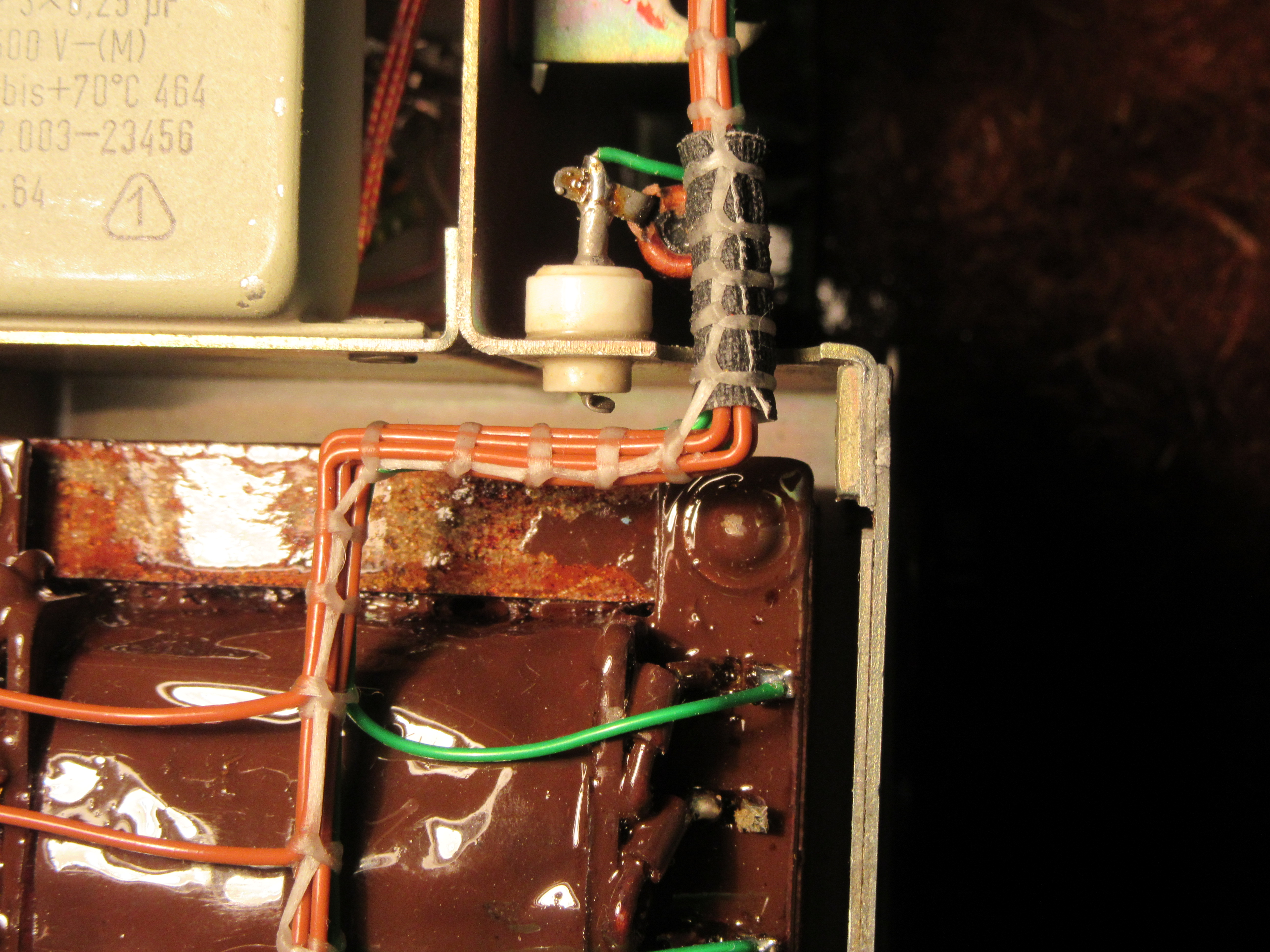
The next step was to repair the defective components. The leaking MP capacitor got a new terminal lug, luckily a small piece of the old terminal was still sticking out. After that, the thoroughly degreased connection was sealed with epoxy resin.
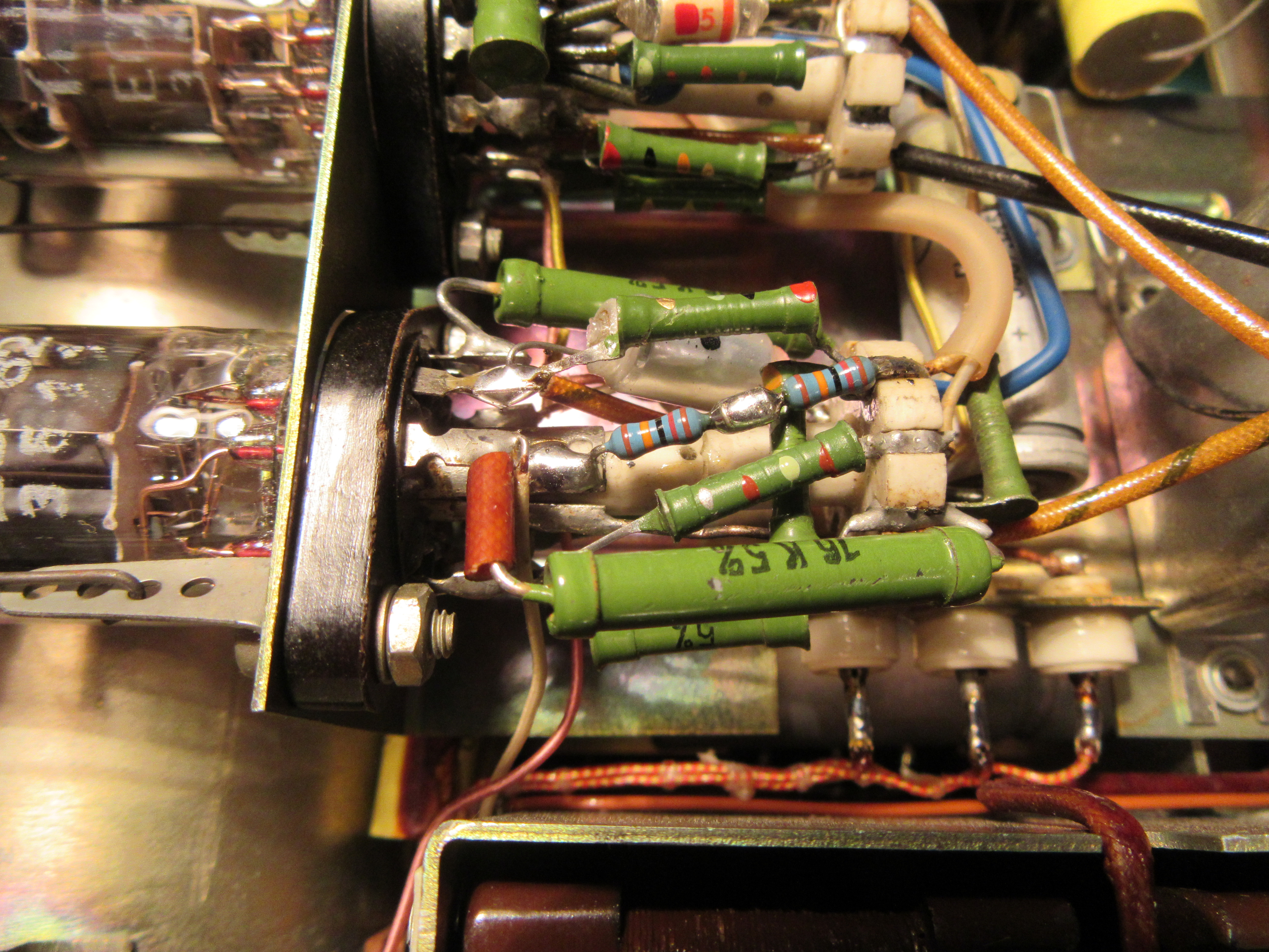
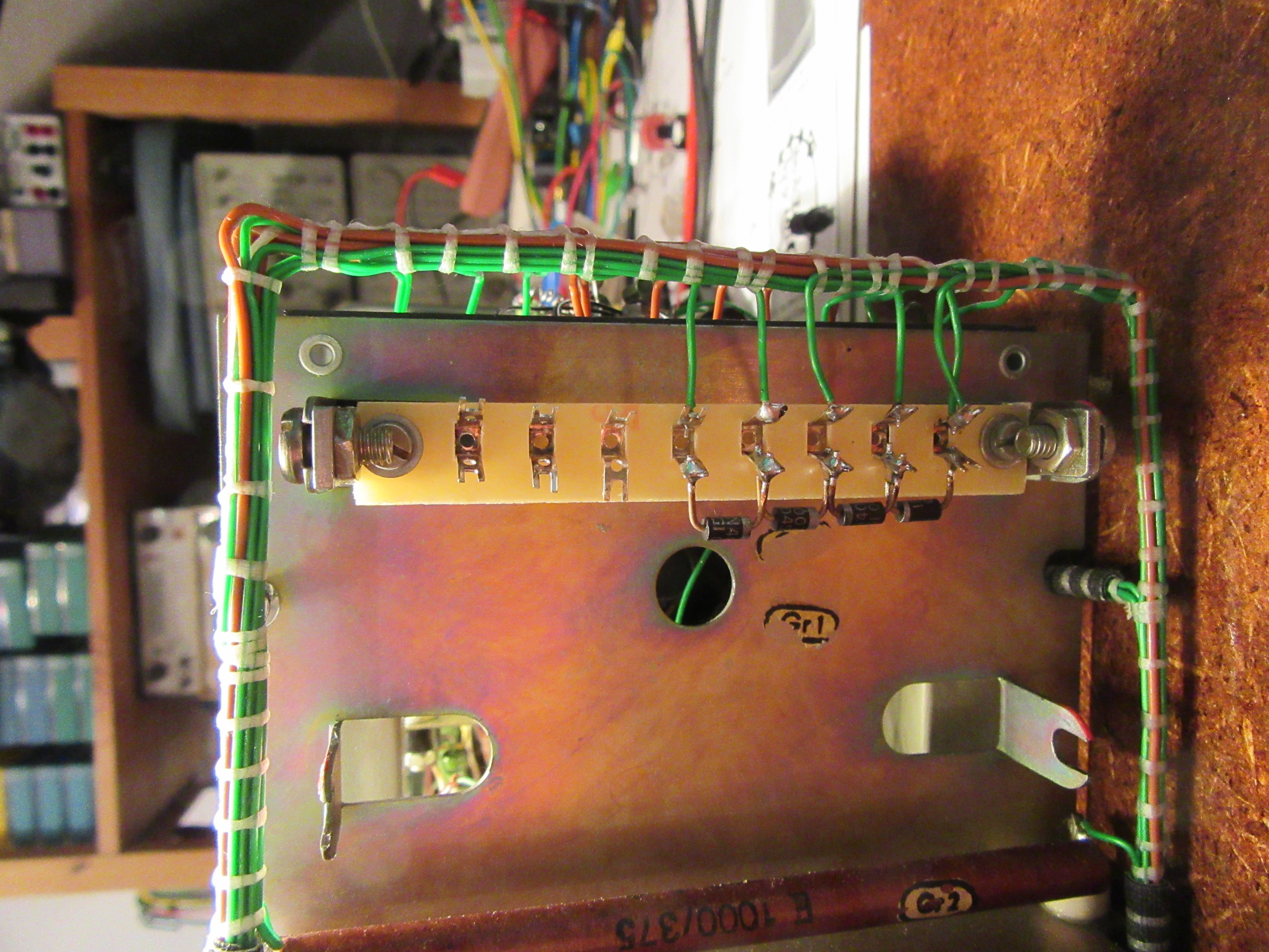
I also glued the broken tube socket with epoxy resin. In the picture you can see that behind one of the two replaced resistors.
It is important to use the “normal” epoxy resin for bonding. This is resin and hardener, which you usually have to mix in a ratio of 100:60 to 100:40. The curing time is 24 to 48 hours. There are also all kinds of fast-curing epoxy-based adhesives. In my experience, however, these do not adhere as well to ceramics and Bakelite.
Bakelite is the keyword for the next repair, the potentiometer with the power switch. Here I could straighten the mechanics again. Fortunately, all fragments of the switch housing were available. Bakelite can also be glued excellently with low viscosity epoxy resin. Afterwards, the glued area is usually more stable than the rest. After cleaning, lubrication and contact care with Neo-Ballistol, the potentiometer works like new again.

Lastly, I made a new rear cover for the second defective potentiometer. In contrast to the original, I made this from aluminum instead of sheet steel. Thanks to my electromechanical training in the 80s, I can do such work relatively precisely.
This saved the components that could be saved. The function of the two defective pots is completely restored and because of the presumably better lubrication, the expected service life is possibly also longer than with the original.
Spare parts
Some spare parts I had to order. The fuse holder is a standard model from the GDR and still relatively easy to find on the Internet. From the tubes ECF82 I was able to purchase a lot of 8 pieces very well preserved copies from Telam at a good price. It was important to me that all tubes are one make. I think this is a good idea for metrology.
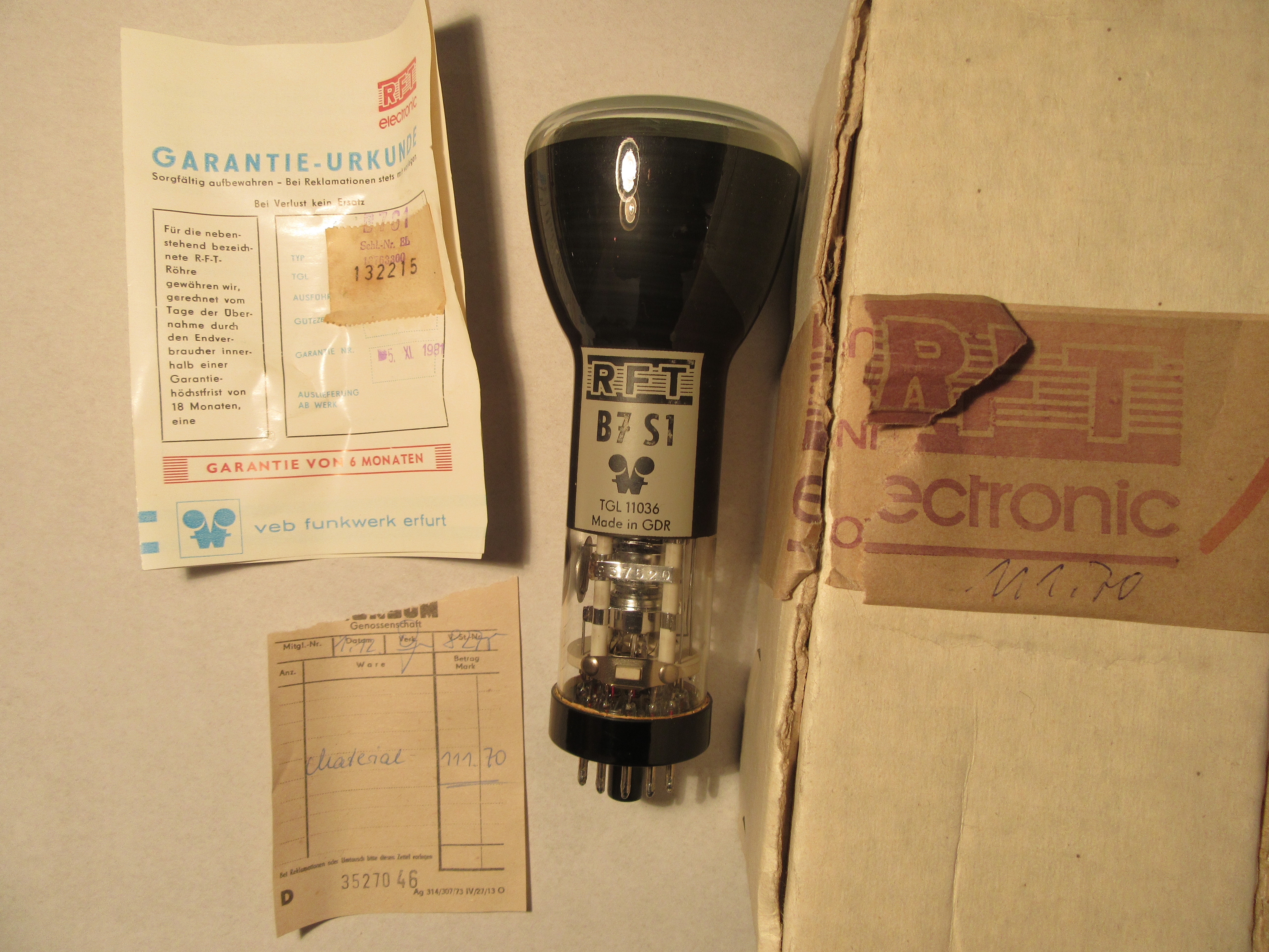
A bit more difficult was to get a cheap picture tube, the B7S1. The offered ones were too expensive for me and that with uncertain function. By chance, I came across an O7S1, compared the base scheme and characteristic values and was of the opinion that the O7S1 is a direct predecessor of the B7S1 from the time before 1945. In the end, I had to find out that this is not so. The base is turned by 180°, the cathode is not led out individually and the three grids have also somewhat different functions. I described the test of this tube in a separate blogpost. So in the end I had to look for a B7S1 and with some luck I found a new and original packed one, even the warranty certificate was still there.
Reconstruction
First I dedicated myself to the power supply. Also to test first if everything is ok with the hard to repair transformers. Unfortunately the selenium rectifiers were missing and I had to replace these two two-way rectifiers then by four diodes 1N4007 in bridge circuit.
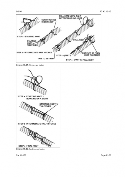
Also, the wiring harness of the power supply was completely missing. I rebuilt it pretty much original. However, instead of the double-wound wire, a modern alternative with ETFE insulation was used. I dedicated a whole blogpost “The wiring harness” to this wiring variant. Of the two electrolytic capacitors in the power supply, one axial 10µF/350V was unsalvageable due to a broken connection directly at the case. In its place, a modern radial variant with 450V dielectric strength is now doing its job.
I reformed the 50µF/350V cup capacitor within two weeks. This worked wonderfully, at nominal voltage it had only 80µA leakage current at the end. I have dedicated a whole article to the forming of electrolytic capacitors.
Unfortunately I did the first test of the power supply without load. Because of this and the lower voltage drop of the new rectifier bridge made of silicon diodes, the anode voltage had about twice the nominal value at no load. It went poof briefly and the elaborately formed cup electrolytic capacitor was history, really a pity. At least I learned that you should never test power supplies of tube devices without load and how to restore a cup capacitor or how to hide a modern capacitor in it. There will be a post about that here soon, too. After this repair the power supply was complete and worked perfectly.
The next step was to restore the other wiring in the unit. In addition, a total of two defective resistors had to be replaced.
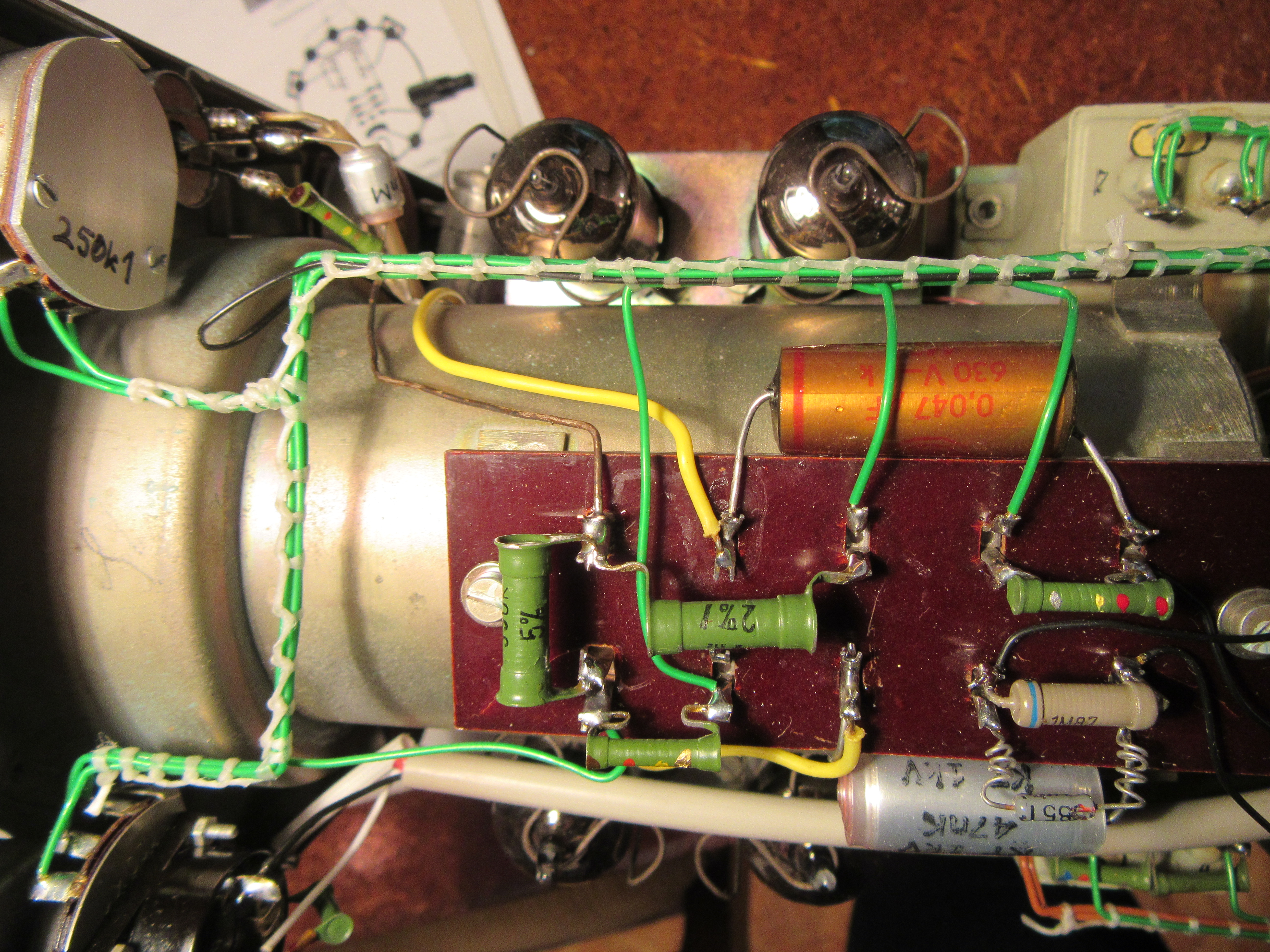
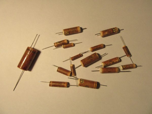
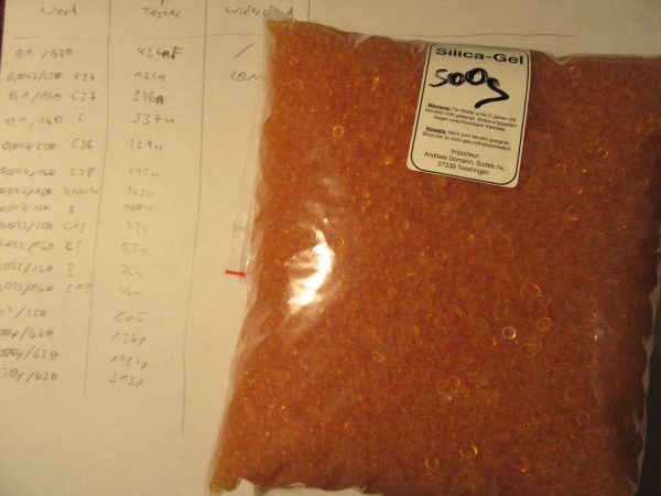
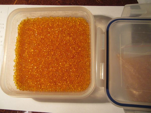
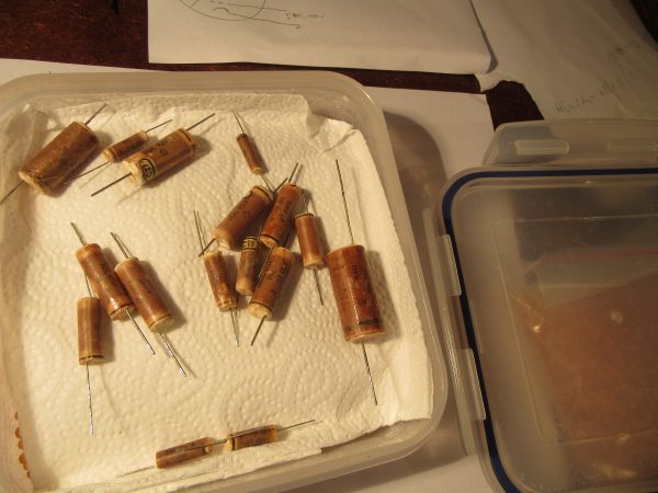
I have exchanged all paper capacitors for safety reasons and replaced them with film capacitors. I was lucky and was able to replenish my supplies thanks to Markus from Hamburg, who offers many different values at “ebay Kleinanzeigen”. But I felt too sorry for the basically still working paper capacitors to throw them away just because they have a slightly too high leakage current. I documented my attempt to make them fit again in the article “Paper capacitors restore“. This is certainly better than replacing them, since some of the circuitry is designed to handle these higher leakage currents.
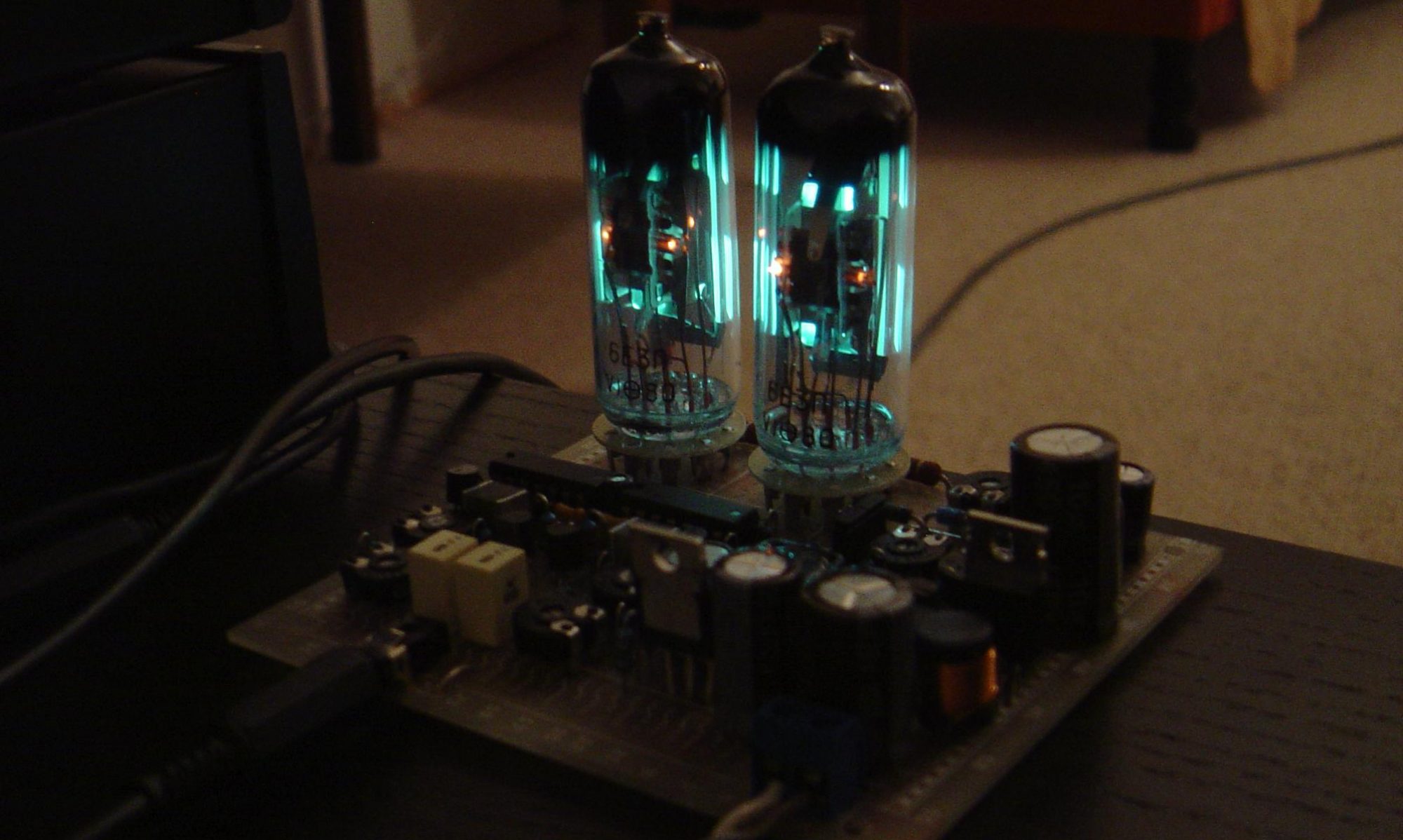
Finally, I just put in the four ECF82 tubes and the picture tube, and voila, everything worked flawlessly right away. Now the front panel and the case are missing and at the end the picture tube should show the time in analog form. But that’s a new project.
 Quelle:
 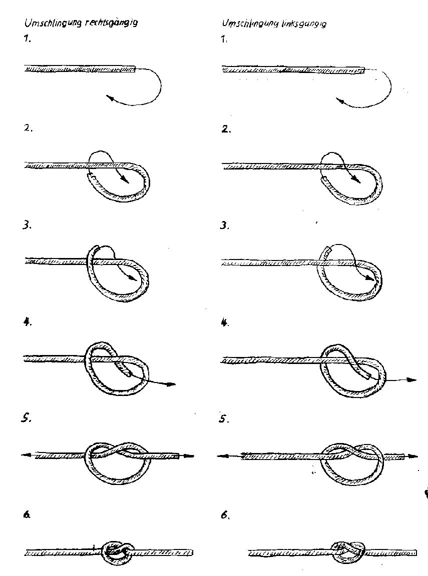 Grundknoten, Quelle: www.mikrocontroller.net
/attachment/49981/Blatt412_Grundknoten.png
Grundknoten, Quelle: www.mikrocontroller.net
/attachment/49981/Blatt412_Grundknoten.png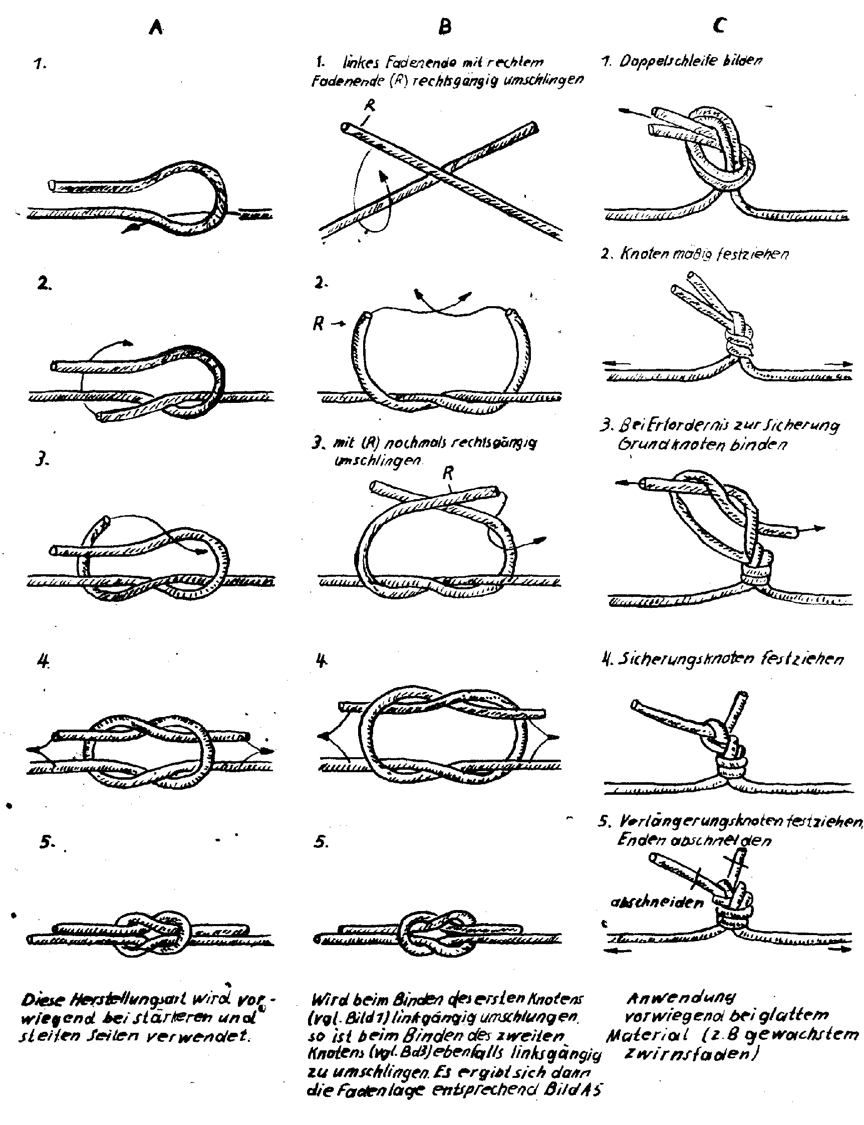 Verlängerungsknoten, Quelle: www.mikrocontroller.net
/attachment/49982/Blatt413_Verlaengerungsknoten.png
Verlängerungsknoten, Quelle: www.mikrocontroller.net
/attachment/49982/Blatt413_Verlaengerungsknoten.png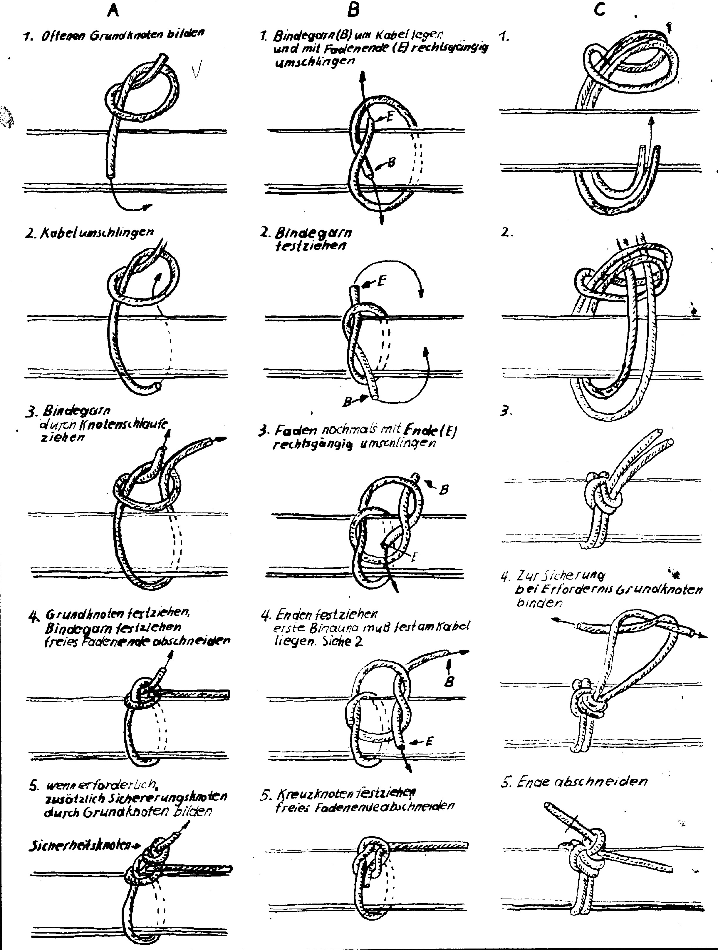 Anfangsknoten, Quelle: www.mikrocontroller.net
/attachment/49983/Blatt414_Anfangsknoten.png
Anfangsknoten, Quelle: www.mikrocontroller.net
/attachment/49983/Blatt414_Anfangsknoten.png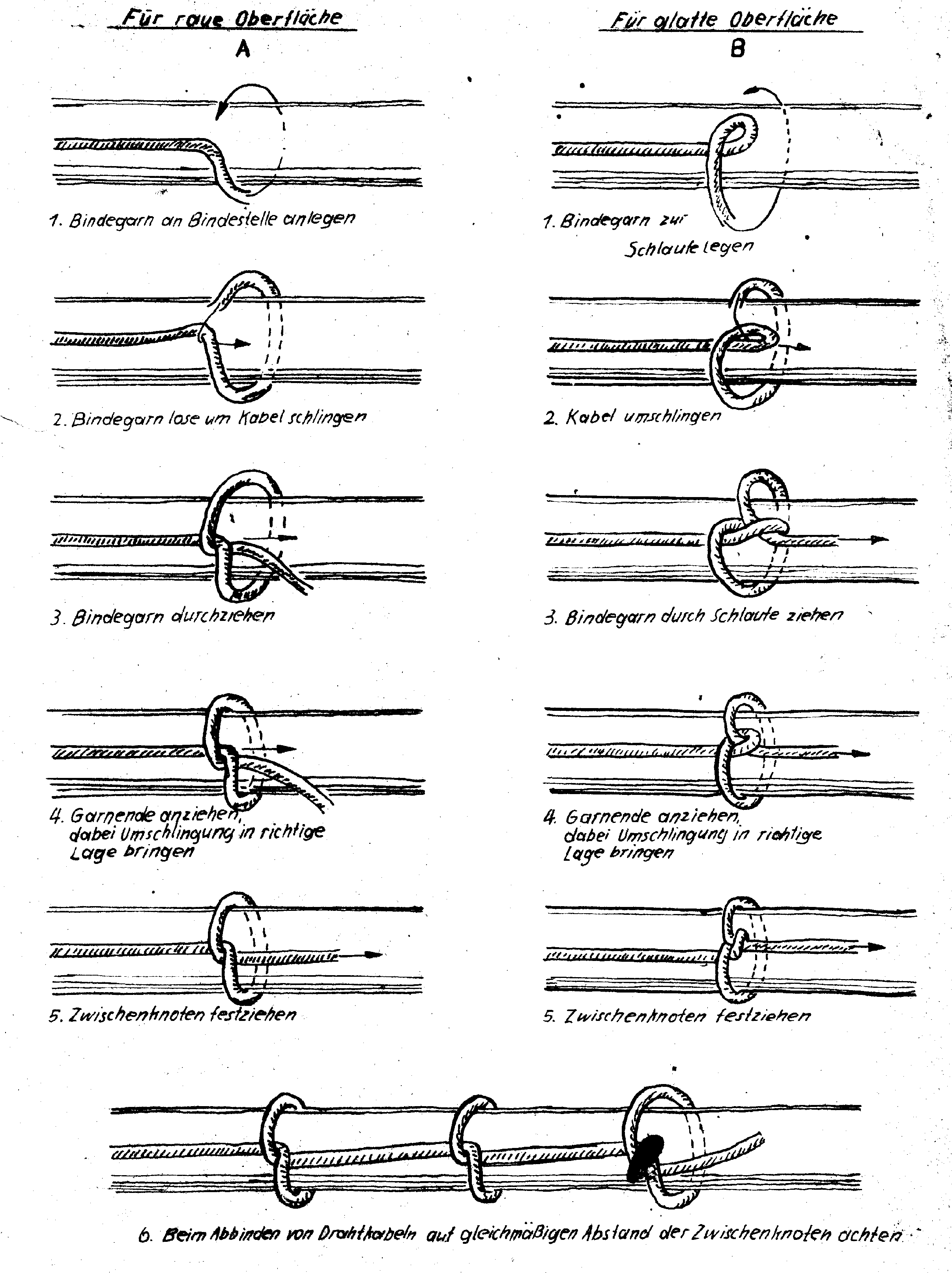 Zwischenknoten, Quelle: www.mikrocontroller.net
/attachment/49984/Blatt415_Zwischenknoten.png
Zwischenknoten, Quelle: www.mikrocontroller.net
/attachment/49984/Blatt415_Zwischenknoten.png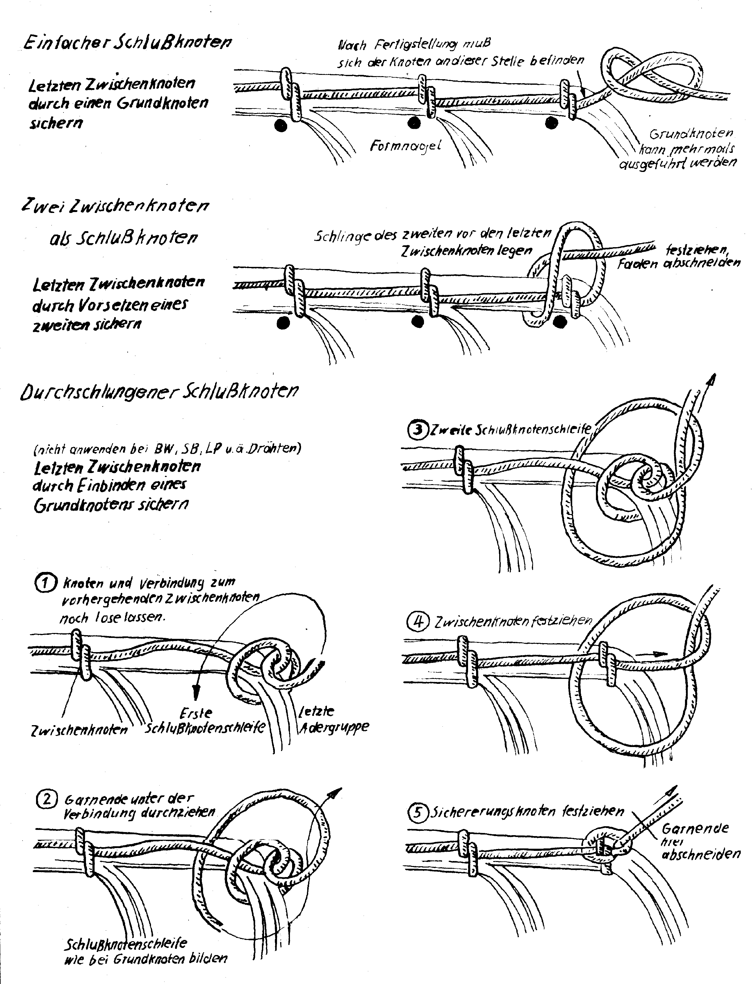 Schlussknoten, Quelle: www.mikrocontroller.net
/attachment/49985/Blatt416_Schlussknoten.png
Schlussknoten, Quelle: www.mikrocontroller.net
/attachment/49985/Blatt416_Schlussknoten.png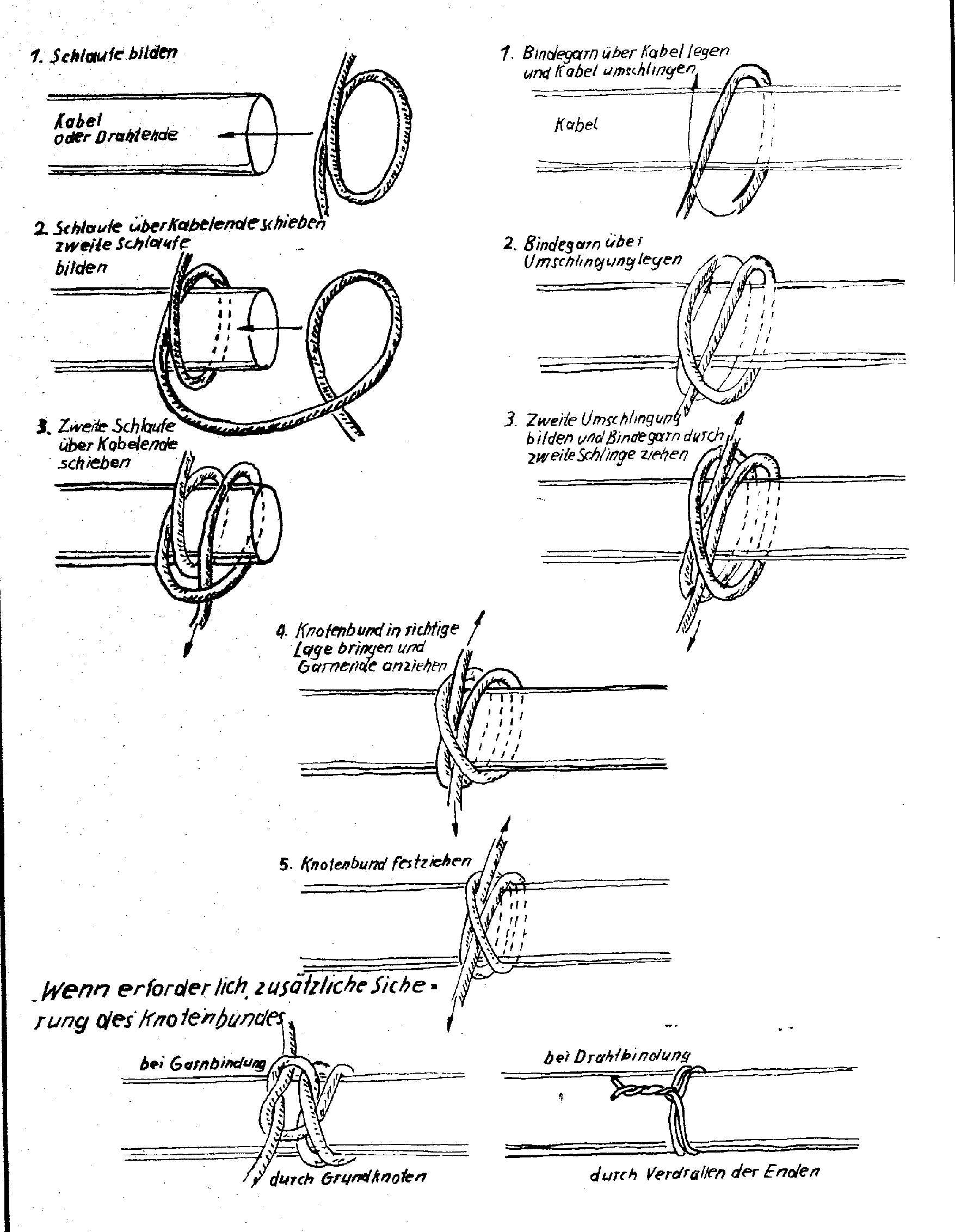 Knotenbund, Quelle: www.mikrocontroller.net
/attachment/49986/Blatt418_Knotenbund.png
Knotenbund, Quelle: www.mikrocontroller.net
/attachment/49986/Blatt418_Knotenbund.png