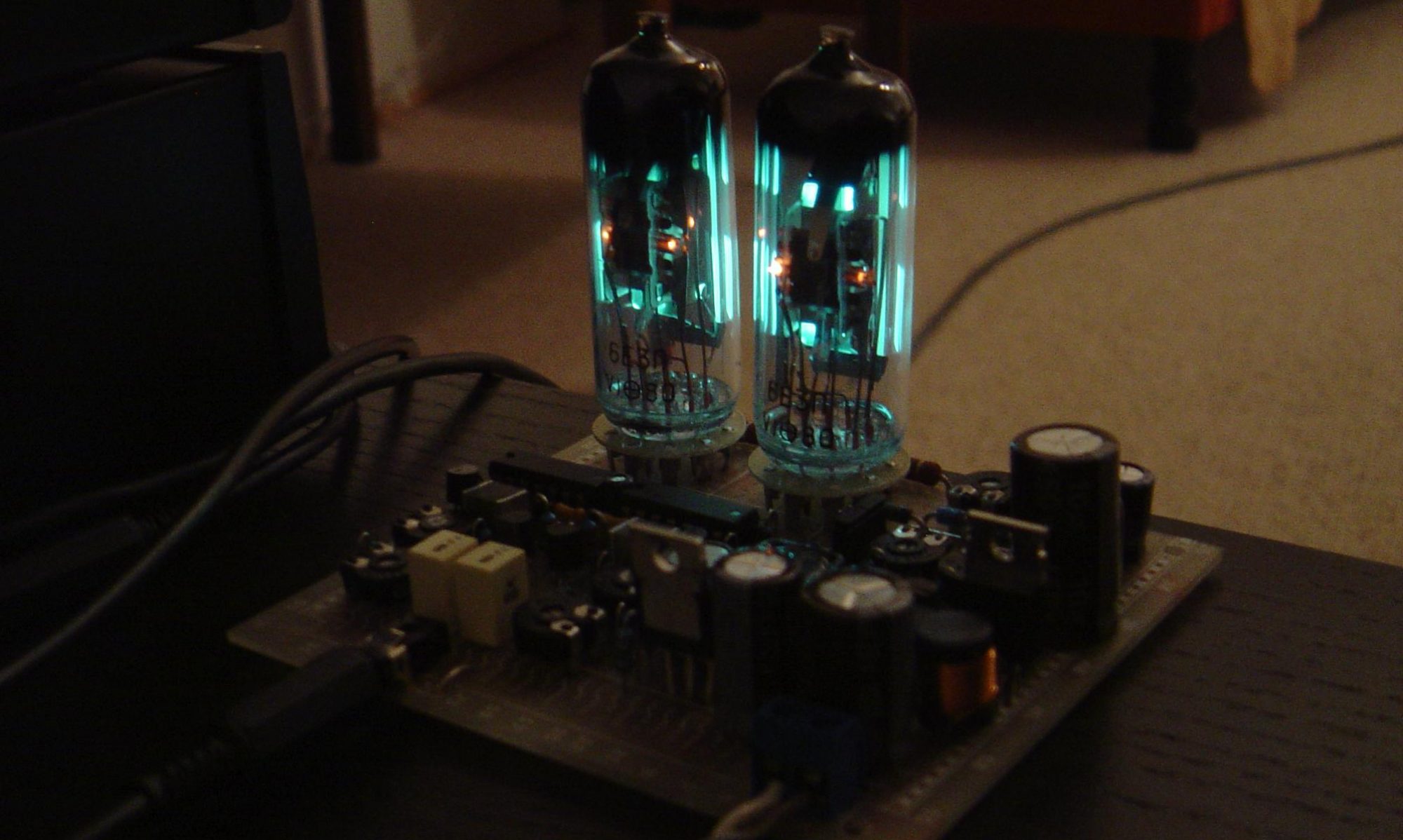
Dieses Projekt aus dem Jahr 2012 ist immer noch aktuell und verbindet das I2C-Interface eines Cypress CY22150 CyberClock PLL-Chips mit einem USB-Port. Dazu habe ich eine passende Steuersoftware mit grafischer Oberfläche zur Programmierung der PLL erstellt, die hier heruntergeladen werden kann.
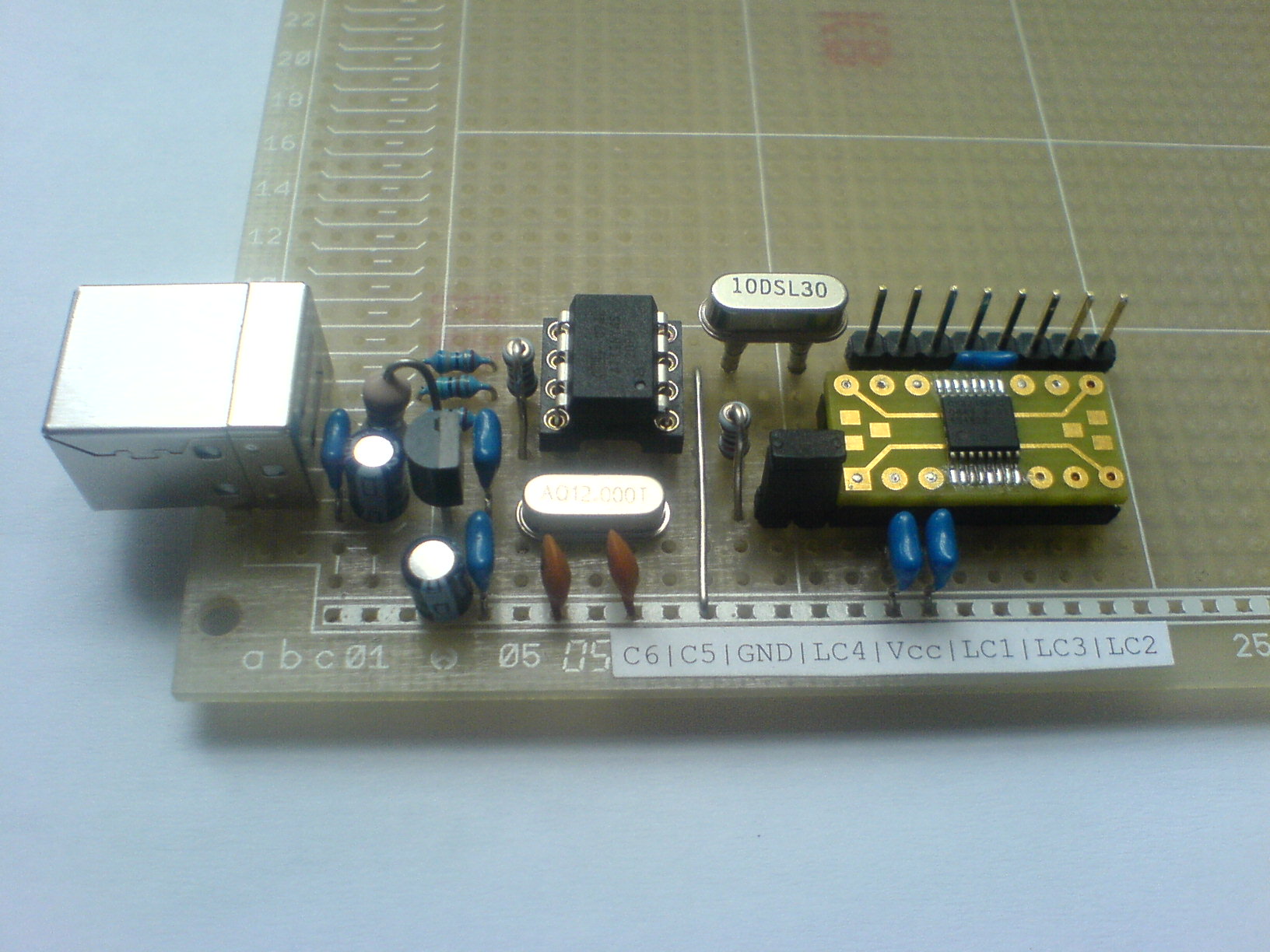
Für das I2C-Interface habe ich „I2C-Tiny-USB“ benutzt, was von Till Harbaum entwickelt wurde mit verfügbaren Treibern für Linux, Windows und MacOS.
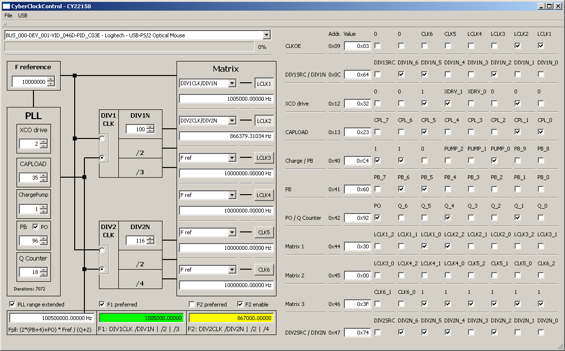
Die Steuersoftware „CyberClockControl“ ist für Linux und Windows verfügbar und möglicherweise für MacOS. Sie ist in C++ geschrieben und mit „Qt Creator“ entwickelt, einer Cross-Plattform Qt IDE von Qt Software. Der Quellcode ist hier veröffentlicht unter der „GNU General Public License“ (GPL).
Software Vorteile:
- Grafische Bedienoberfläche für verschiedene Plattformen
- Erzeugung von zwei verschiedenen Frequenzen mit nur einer PLL
- besserer Algorithmus für die Berechnung von PB und Q als in der Software „CyberClocks“ vom Hersteller Cypress (kleinerer Q-Wert)
- Veränderung und Berechnung der Chip-Register in Echtzeit
Das Schaltbild kann hier heruntergeladen werden.
CY22150_i2c-tiny-usb_schematics
Vorkompilierte Programme sind für linux/x86_64 und win32 verfügbar. Für win32 muss der libusb Treiber aus dem Sourcecode installiert werden.
Nachtrag vom 6.11.2022:
Ich habe eine neue Version der Software zur Verfügung gestellt für linux/x86_64 und win32 mit der Änderung, dass nun die I2C-Adresse abweichend vom Standardwert 0x69 frei gesetzt werden kann. Der Grund ist, dass die Adresse beim CY22150 per Software konfigurierbar ist und die Standardeinstellungen in einem internen Flash-Speicher abgelegt sind. Somit kann es vorkommen, dass einem Chips unterkommen, die mit einer abweichenden Adresse konfiguriert sind. Leider hält Cypress den Algorithmus zum Programmieren des Flash geheim. Ebenso findet sich keinerlei Information über die Möglichkeit der Änderung der I2C-Adresse im Datenblatt. Aus Sicht eines Ingenieurs ist dieses Zurückhalten von Informationen für ein Produkt einfach nur peinlich. Und vielleicht zu Recht ist die Firma Cypress mittlerweile Geschichte. Es wäre leicht möglich, das alles mit Reverse-Engineering herauszubekommen, allein mir fehlt der Ehrgeiz. Die I2C-Adresse steht – natürlich undokumentiert – im Konfigurationsspeicher an Adresse 0x11, verodert mit 0x80. Hier kann die I2C-Adresse zur Laufzeit jederzeit geändert werden. Nach Abschaltung der Betriebsspannung wird die Adresse allerdings wieder auf den Standard zurückgesetzt.
Wer nun tatsächlich den Flash eines CY22150 ändern will, braucht zwei Dinge:
- Einen „CY3672-USB“ Programmer, der allerdings neu nicht mehr erhältlich ist und
- die Software „CyberClocks“, welche nach Registrierung kostenlos hier erhältlich ist.
Hier findet sich eine Info des Herstellers zur Flash-Programmierung der ICs.
Hello! I express my gratitude for your project „Cyberclock Cy22150“. I collected „i2c-Tiny-USB“- everything worked, I checked the test with a display 1602. I ask you to help me, I hope it will not be difficult for you. My problem: I came across a CY22150 chip with an address on the 0X6AH bus (instead of 0X69H by default). My request to you: compile for me a program for Windows with address 0x6ah. I am a radio amateur, I have difficulty programming. As I understand it, you need to change in the „i2c_usb.h“ file value 0x69 by 0x6a
„// CY22150 Chip Address
#define CY22150_ADDR 0x69 “
And then get the file „CyberclockControl.exe“
I hope for your help.
By the way, maybe you know how to change the I2C address from 0x6a to 0x69 in the CY22150 chip itself?
This would completely solve my problem with the device where CY22150 is used !!!
Hi Dmitry,
I wrote an addendum at the end of the article and modified the software to change the I2C-Address. Hope that helps.
Best,
Uwe
Hello. Thank you so much for taking the time to help me.
CY22150 began to be determined – to respond to Skan – Open usb !!! (frequency = 3.597Mhz).
But my expectations were not met, CY22150 – does not remember the state of the frequency 3,597 Mhz
after power off.
(does not remember in its EEprom).
So the question arises – should CY22150 remember the frequency value after using CyberClockControl ???
]]]]]]]]]]]]]]]]]]]]]]]]]]]]]]]]]]]]]]]]]]]]]]]]]]]]]]]]]]]]]]]]]]]]]]]]]]]]]]]]]]]
I read the forum on your link and found interesting information.
Here is the quote:
—————————————————
https://community.infineon.com/t5/Clocks/CY22150-Jedec-File-Analysis/m-p/182577
Anonymous
Not applicable
Mar 31, 2012 12:57 PM
CY22150 Jedec File Analysis!
———————————————————–
If you look at the jedec file for CY22150, although the format may not be obvious,
it’s also not complicated. Starting with the first block:
L00064
0101101000000001000000000000000010000100
0000011000001000100010001000000011101100
00110000000000000000000000000000*
In the first line, 64 is the (decimal) bit address of the first bit. Divide this value
by 8 to get the byte address. So this string of bits begins at register address 8.
Divide the bits into groups of 8, representing byte values.
The bits in each byte are ordered MSB to LSB (left to right),
so they are shifted into the I2C port in exactly the order shown.
White space (spaces and carriage returns) are ignored. The above data is shown below as a series of bytes.
I2C
address
08H 01011010
09H 00000001
0AH 00000000
0BH 00000000
0CH 10000100
0DH 00000110
0EH 00001000
0FH 10001000
10H 10000000
11H 11101100
12H 00110000
13H 00000000
14H 00000000
15H 00000000
There is a gap of unused addresses, then the next block of data starts at L00512.
512 / 8 = 64 (decimal) = 40H
Similar breakdown applies for further addresses. So the bits in groups of 8 following „L00512“
in the JEDEC file start at 40h and go to FFh. After L00512 shift in 40h to 47h. Settings after
that do not matter.
]]]]]]]]]]]]]]]]]]]]]]]]]]]]]]]]]]]]]]]]]]]]]]]]]]]]]]]]]]]]]]]]]]]]]]]]]]]]]]
I have written two files to CyClockRT *.Jed with different I2C addresses: 1)69h , 2)6Ah.
and compared.
69h=(0)1101001, and (1)1101001 =E9h
6Ah=(0)1101010, and (1)1101010 =EAh
The changes are present at 11h !!!!!
Only the first bit is different, it always = 1.
Question : is it possible to form a command to write over I2C :
Device with address 6Ah (CY22150), write the value E9h to address 11h. ???
]]]]]]]]]]]]]]]]]]]]]]]]]]]]]]]]]]]]]]]]]]]]]]]]]]]]]]]]]]]]]]]]]]]]]]]]]]]]]]]]]]]]
I tried (for the first time!!) write a sketch
for Arduino to change the device address(CY22150).
Here’s what happened :
——————————–
/*
sketch_CY22150_Change I2C Address
*/
#include
void setup() {
Wire.begin();
Serial.begin(9600);
while (!Serial);
Serial.println(„\CY22150_Change I2C Address“);
}
void loop(){
Wire.beginTransmission(0x6A);
Wire.write(0x11);
Wire.write(0xE9);
Wire.endTransmission();
delay(100);
}
————————————————
The address is changing!!!
But unfortunately, as in your program,
the change is not saved in the EEprom(cy22150).
After removing the power – again 6A….
Maybe try not to write E9h =(1)1101001,
but to write 6Ah=(0)1101010 ???