First, I have to justify myself to anyone who asks, “Why the heck is he writing in such detail about restoring capacitors?”
From my point of view, the two most common problems that cause old devices to give up the ghost are primarily defective capacitors and, in second place, corroded contacts of mechanical components such as switches, relays or potentiometers. I will certainly write an article on the latter this year. The capacitors, in particular the electrolytic capacitors (short: elko) I dedicate myself here. Some time ago I started an experiment with paper capacitors, which is still running. The other two common capacitor types – ceramic and film capacitors – are much more durable than those with paper or electrolyte, which is why I have to replace them only in very rare cases and do not report about them here.
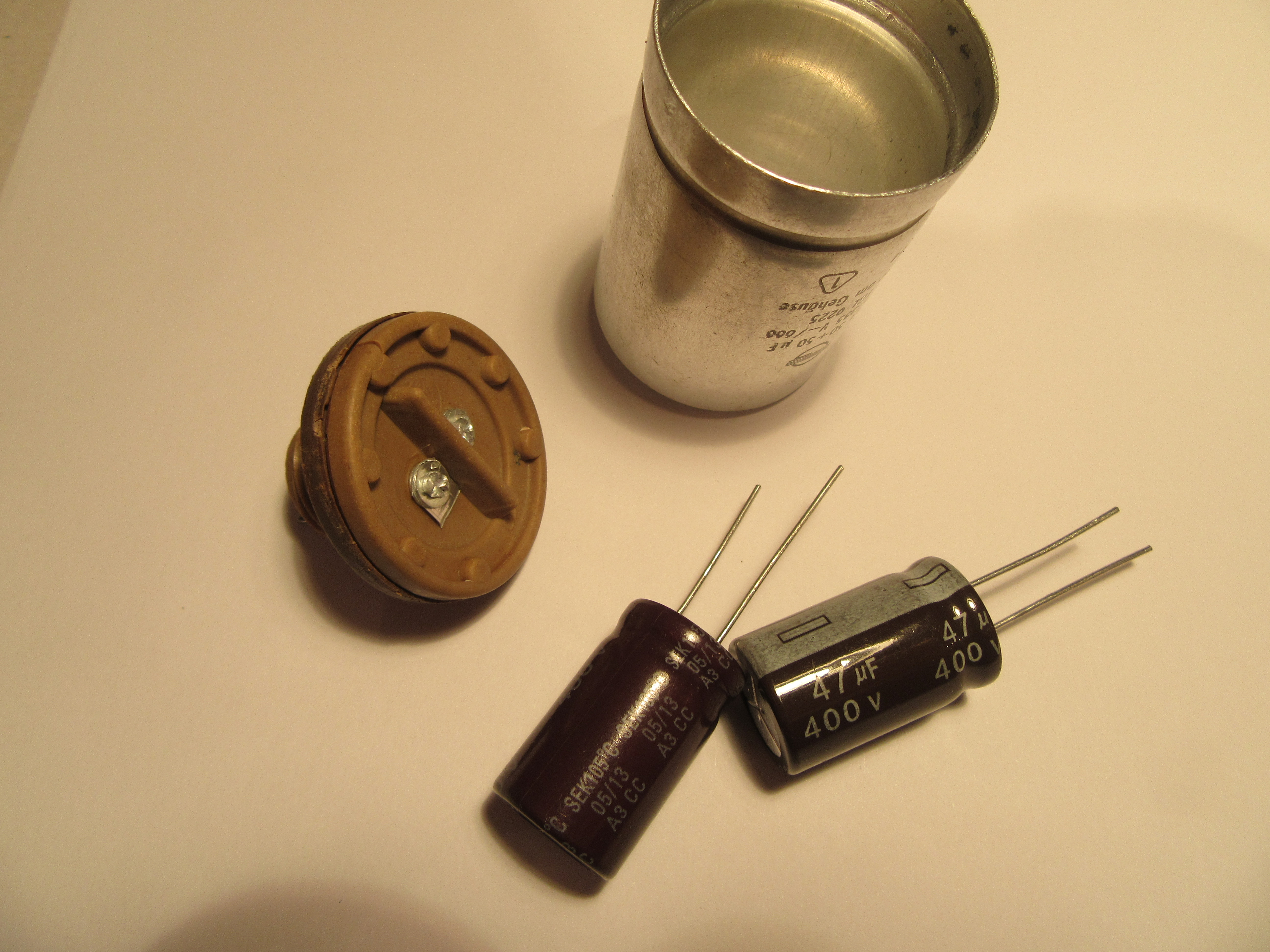
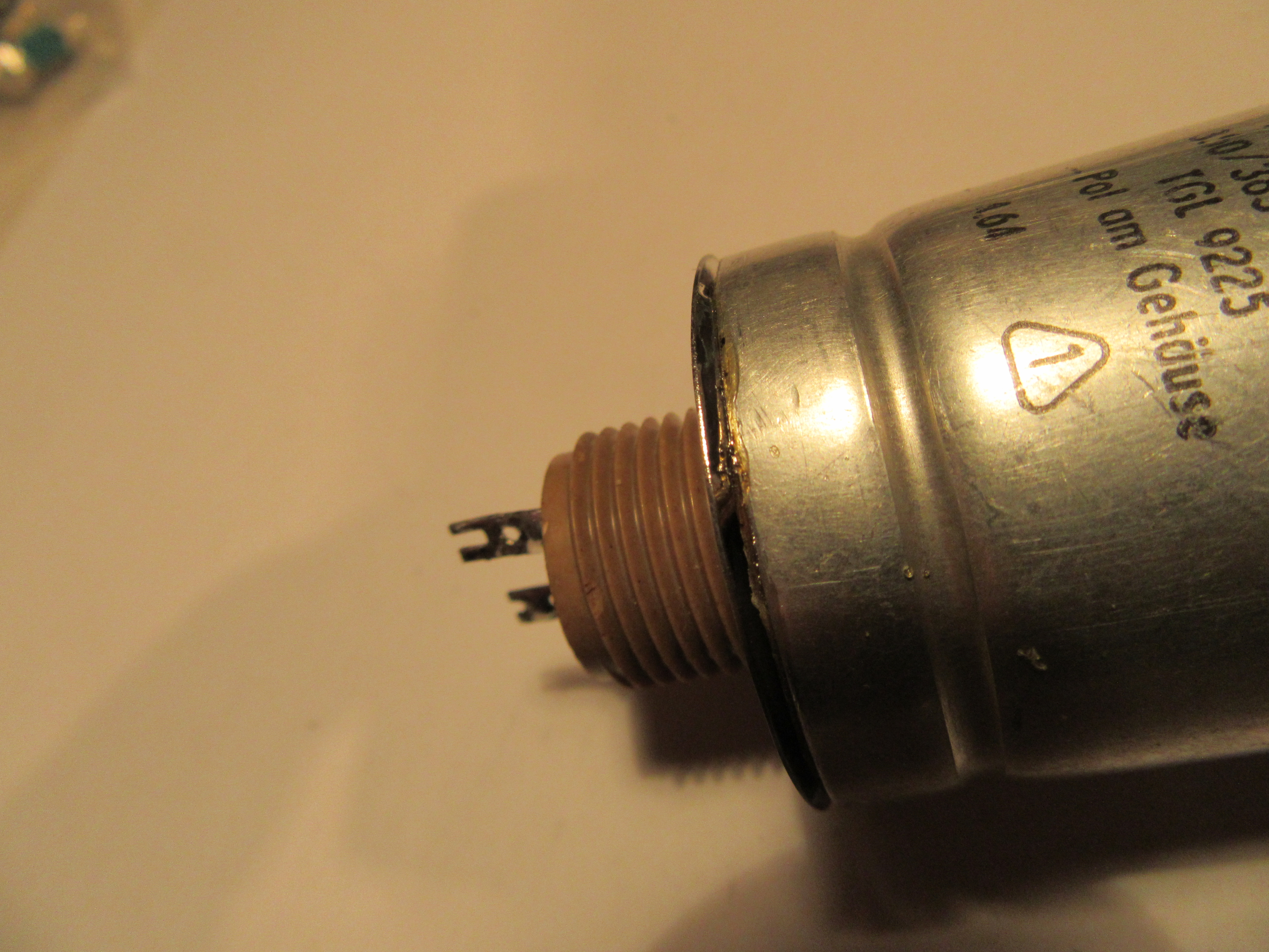
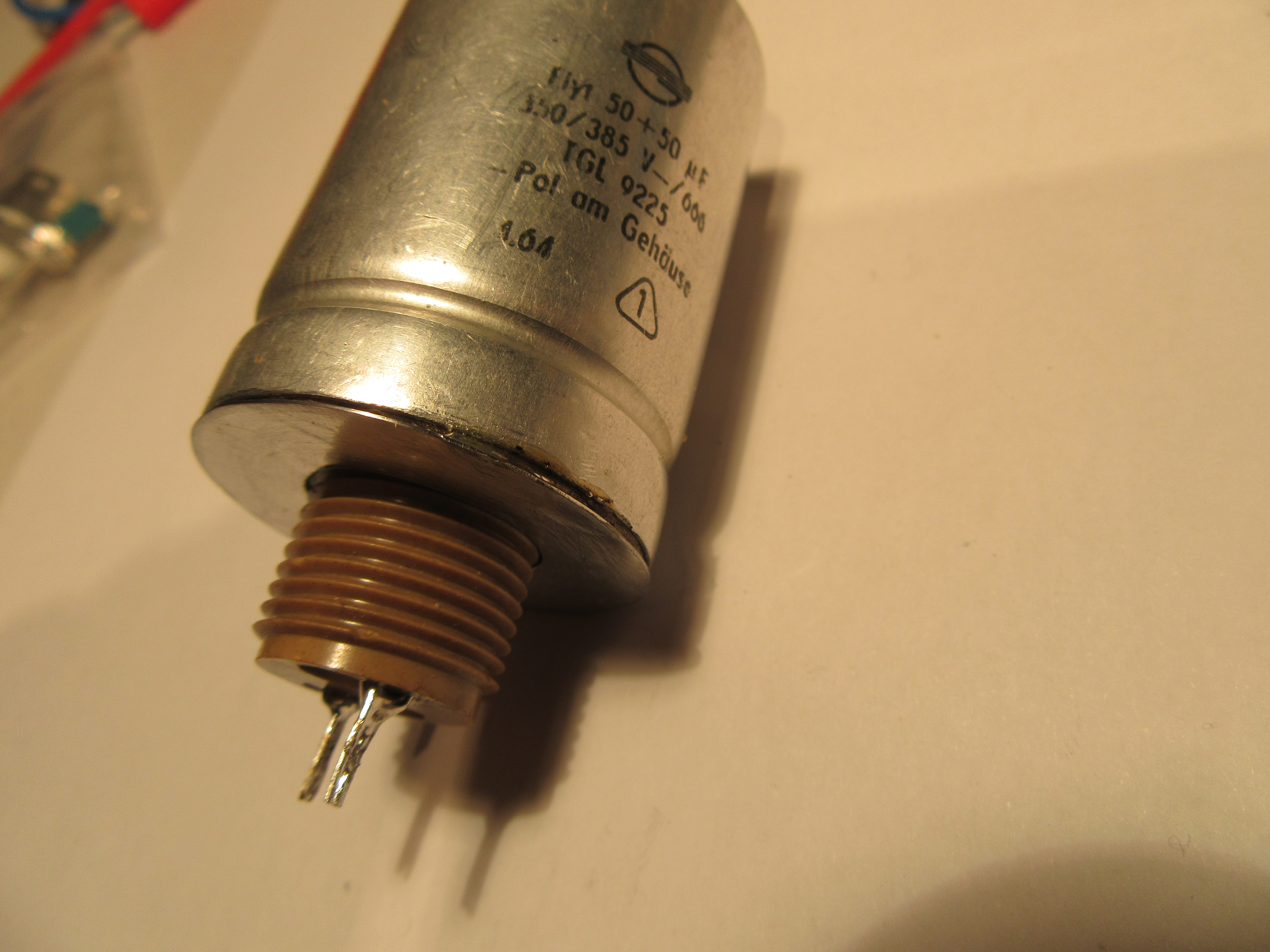
The protagonist of this article is a 50+50µF/350V power supply electrolytic capacitor from a tube radio “Saalburg 5170” from VEB Stern-Radio Sonneberg, which I had repaired for my friend Axel in early 2015.
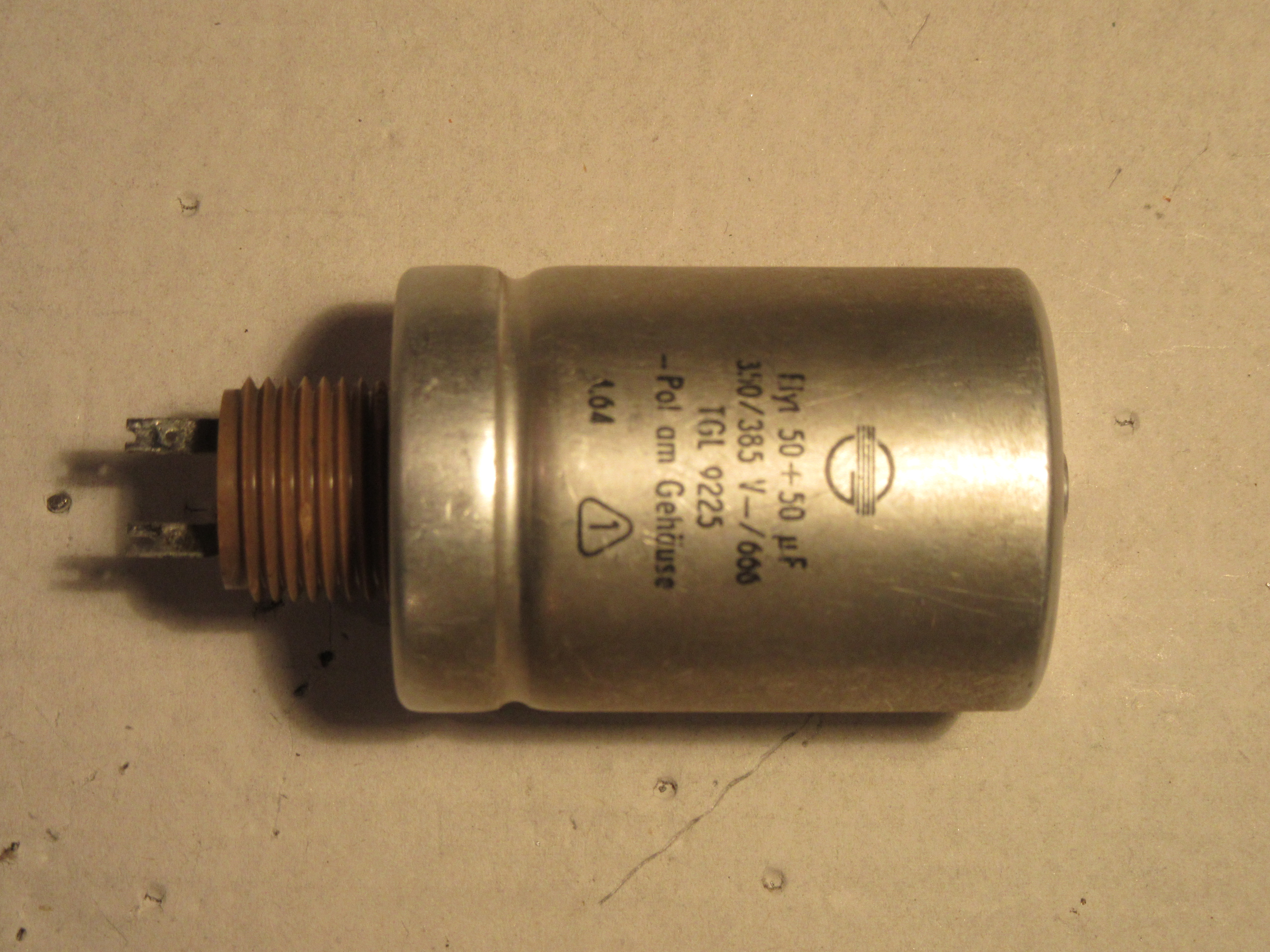
The radio must have been humming since we bought it, and in fact we found a manufacturing defect that is now being fixed after 50 years. The capacitor was not flanged correctly, so the electrolyte leaked.
Structure of electrolytic capacitors
But now to the topic. I can’t summarize what you need to know better than Wikipedia.
https://de.wikipedia.org/wiki/Aluminium-Elektrolytkondensator
The most important point is that it is an aluminum foil, which has a thin oxide layer on one side. The whole winding is in a liquid, the electrolyte. This ensures that the oxide layer is formed in an electrochemical process. An electric field or voltage is necessary for this. The process of building up the oxide layer is called forming. Another important term is leakage current, which refers to the current that passes through this oxide layer, so to speak. The lower the leakage current, the better. The higher the current, the more power loss we have in the capacitor, which can lead to heat generation and, in extreme cases, even explosion.
Defects
The three most common defects are:
- Degradation of the oxide layer after a long period without operation
- Leakage of the electrolyte or drying out
- Short circuit or breakdown
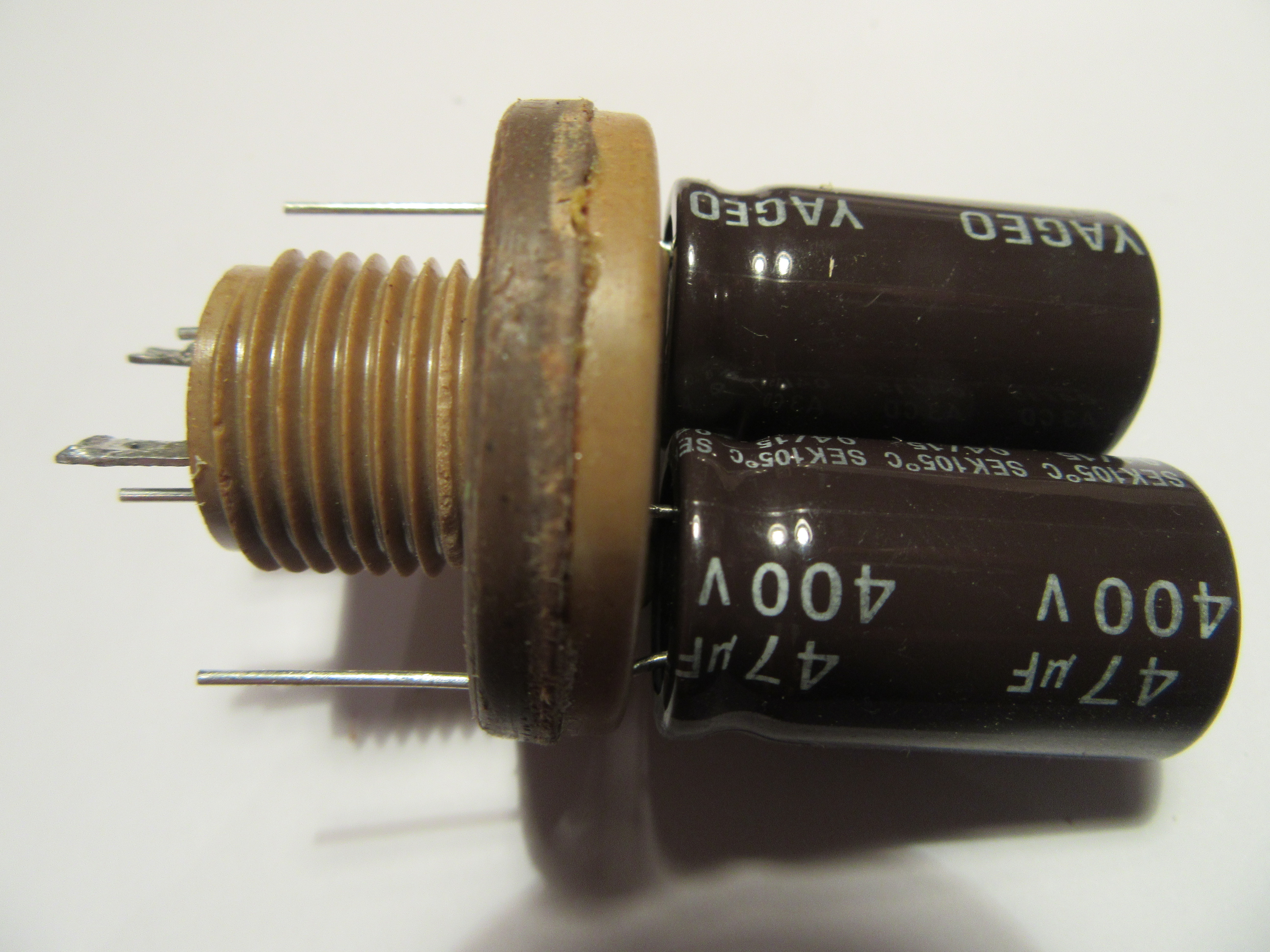
In the case of point one, the capacitor can be reformed. In the case of points two and three, the component is lost. But you can save the case and replace the inner part with a capacitor of current design. This way it is at least possible to preserve the outer appearance and the function, which is an important point for restorations.
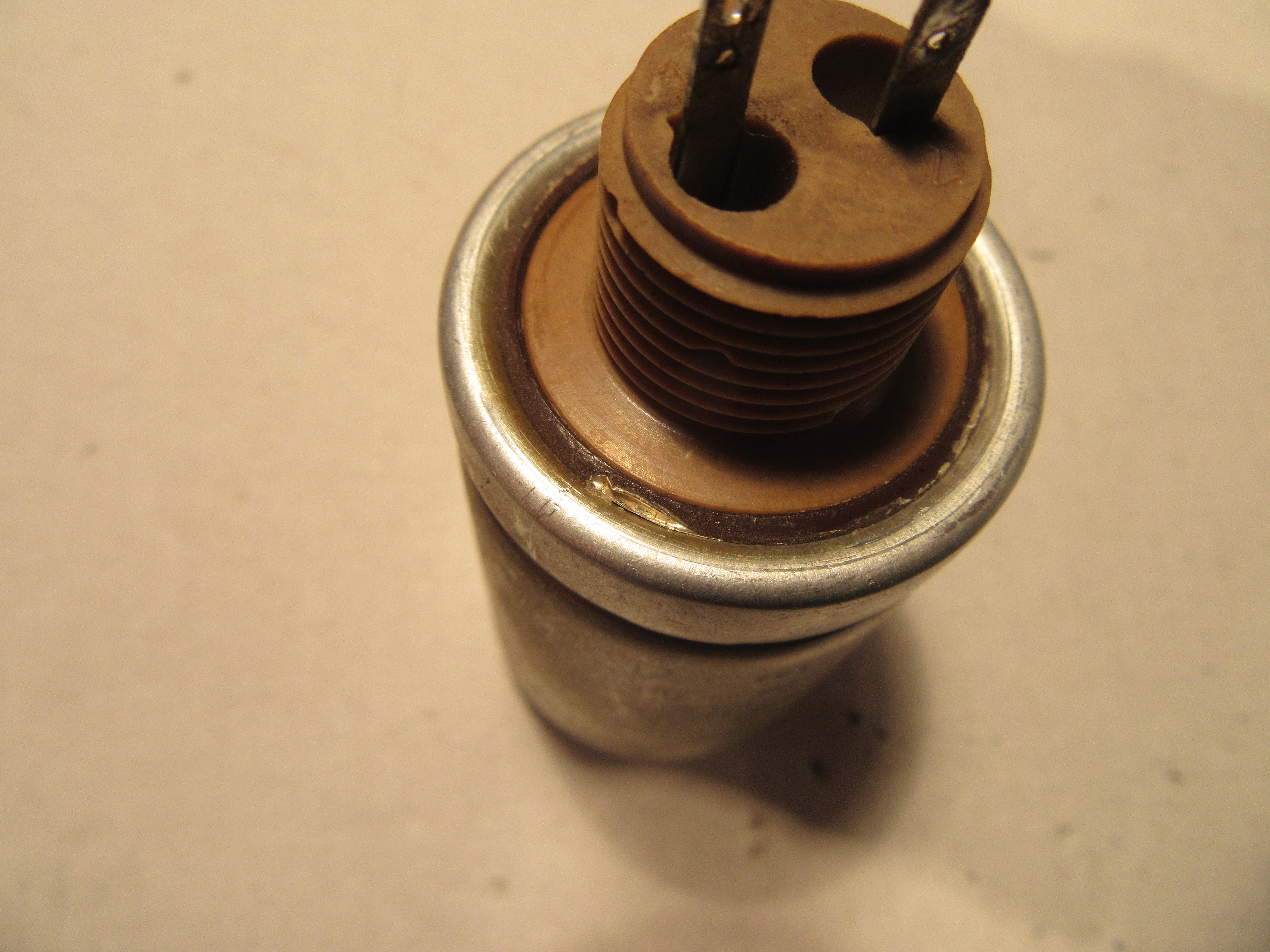
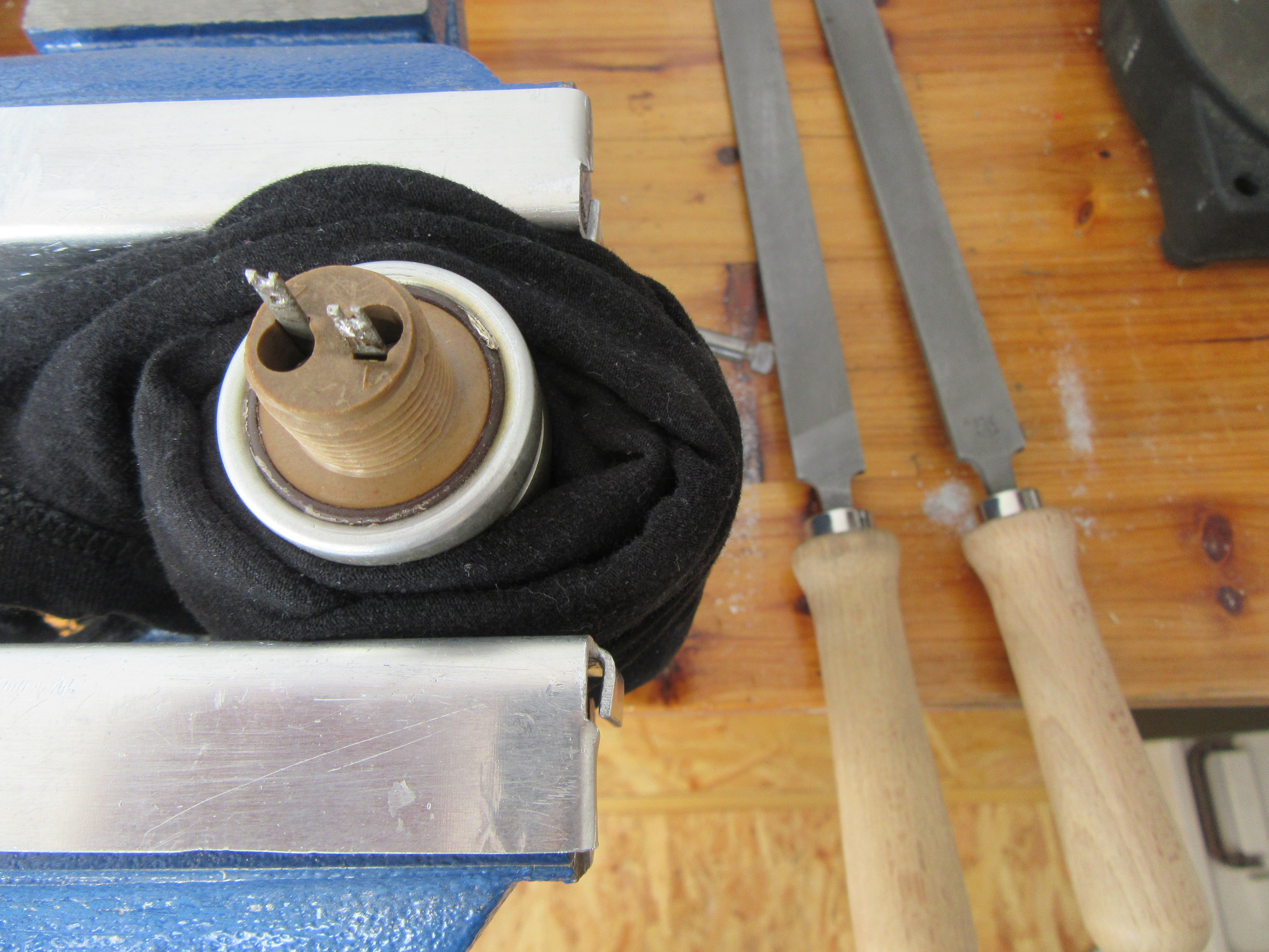
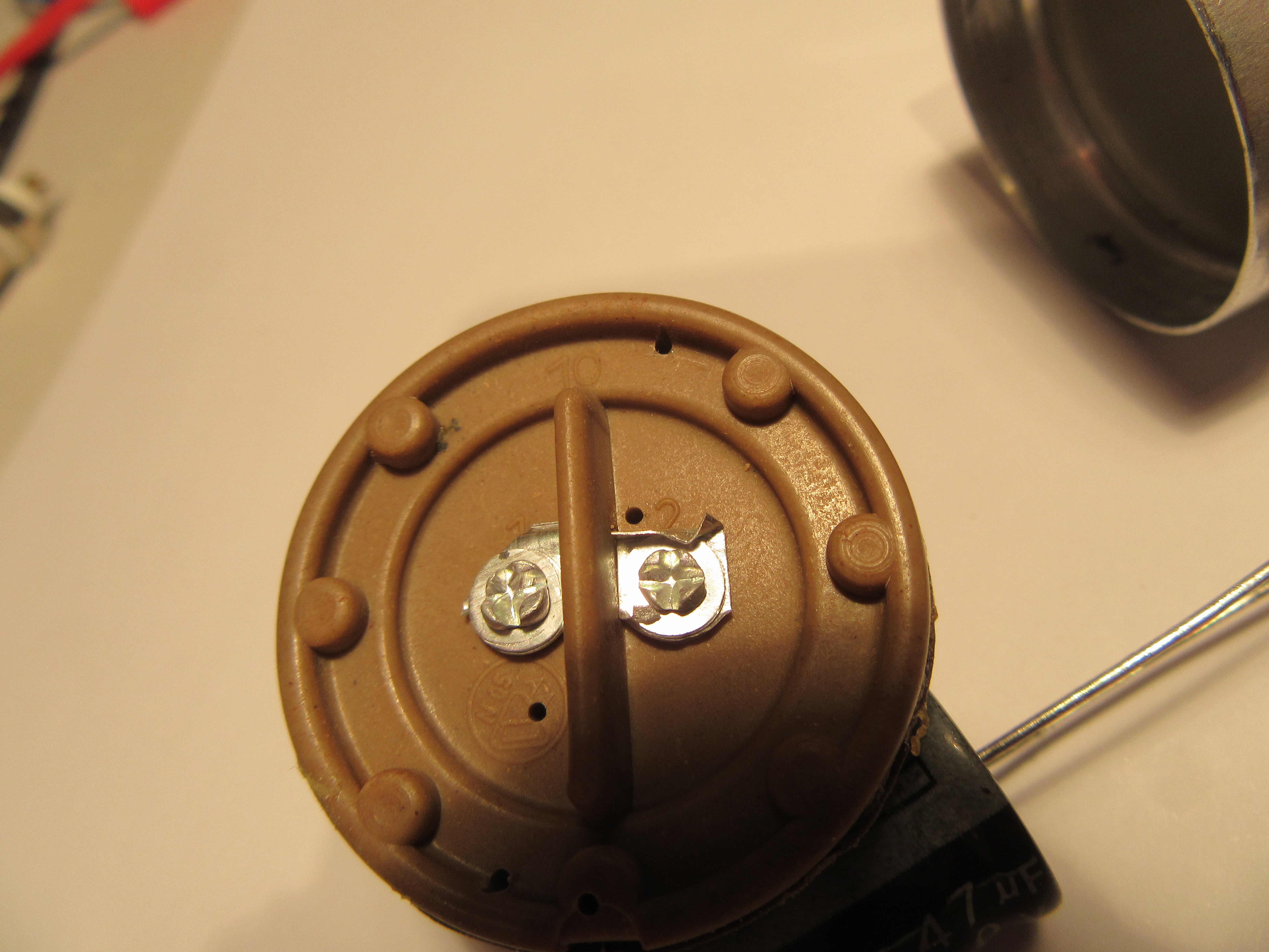
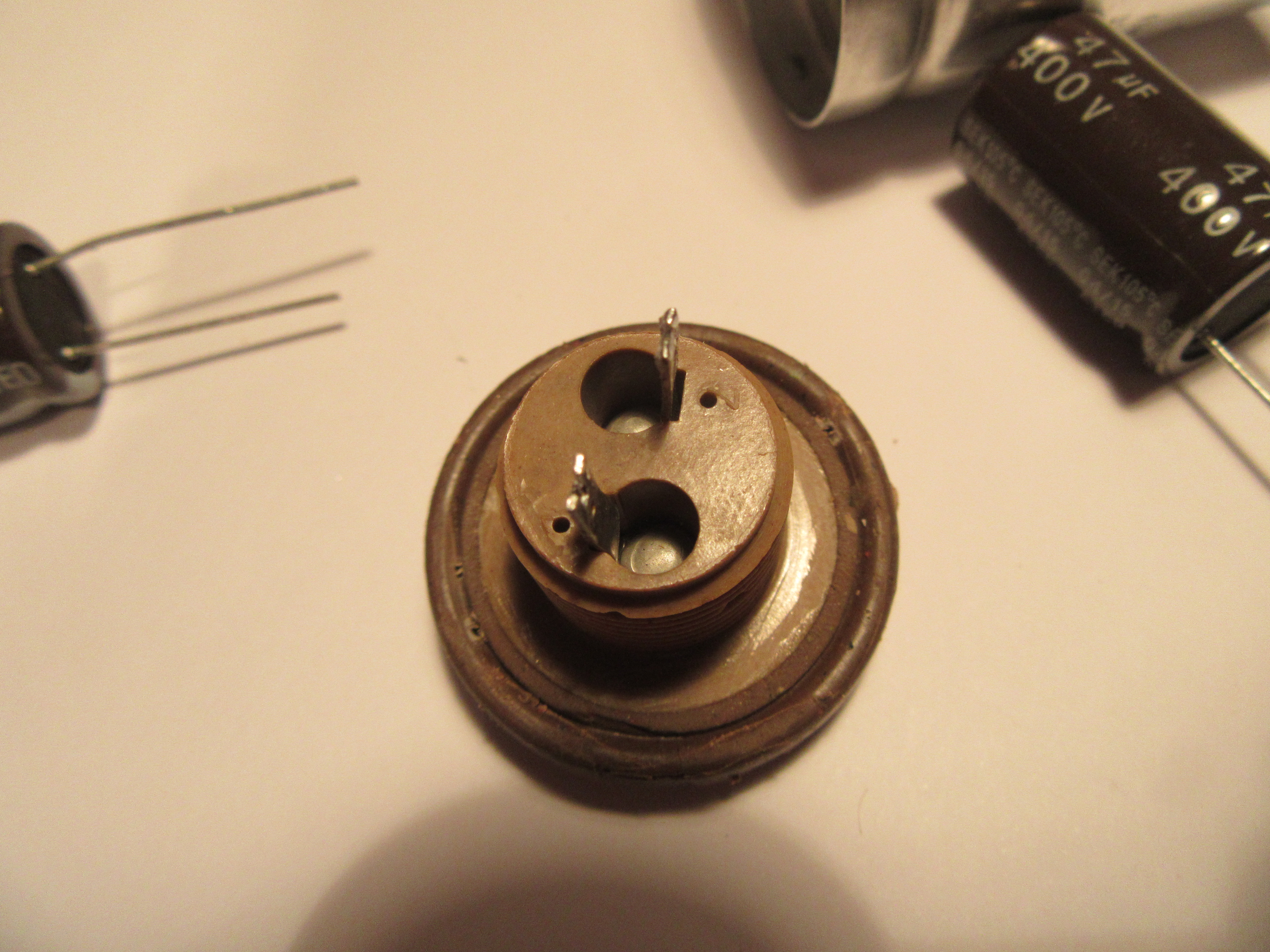
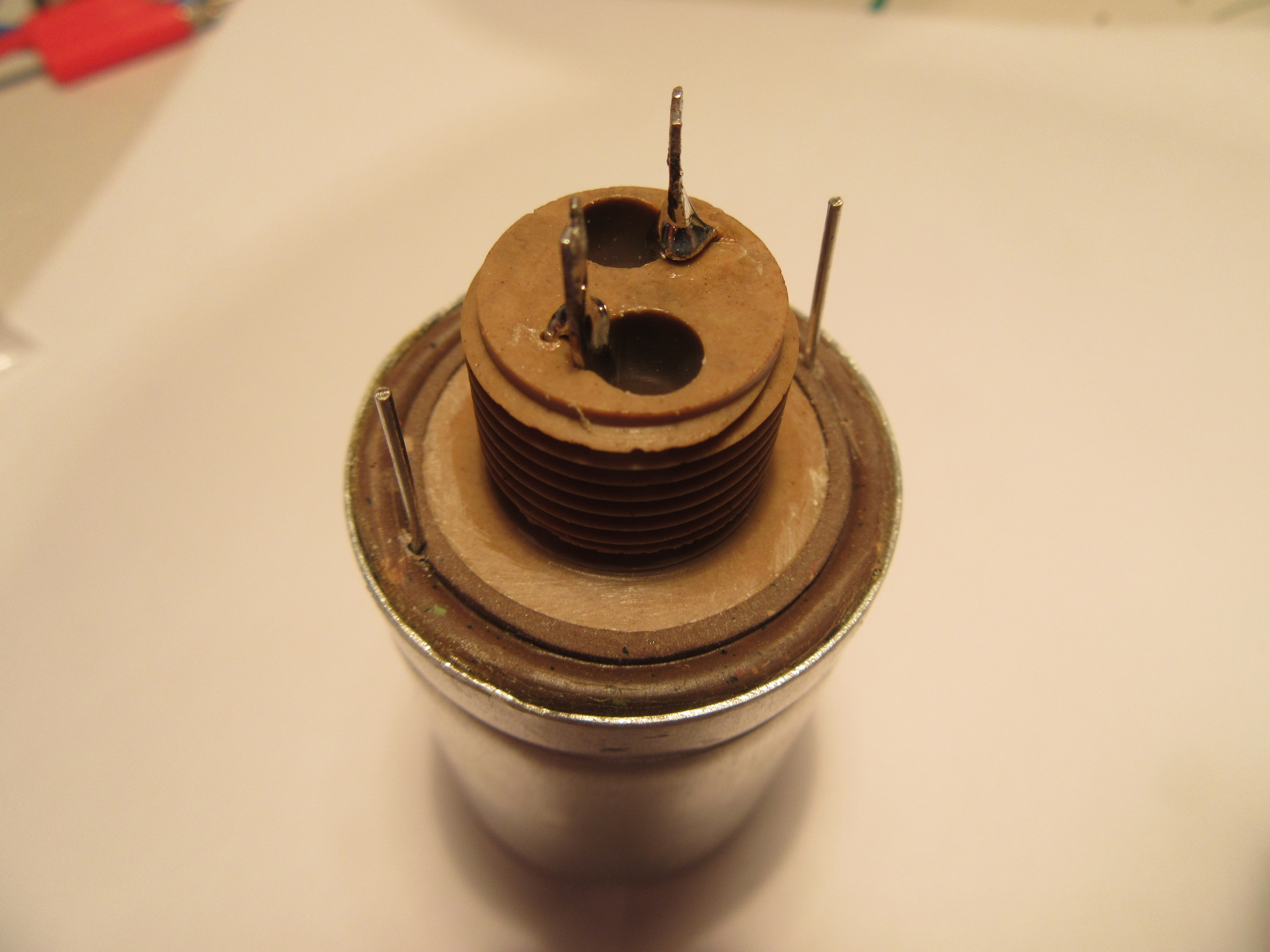
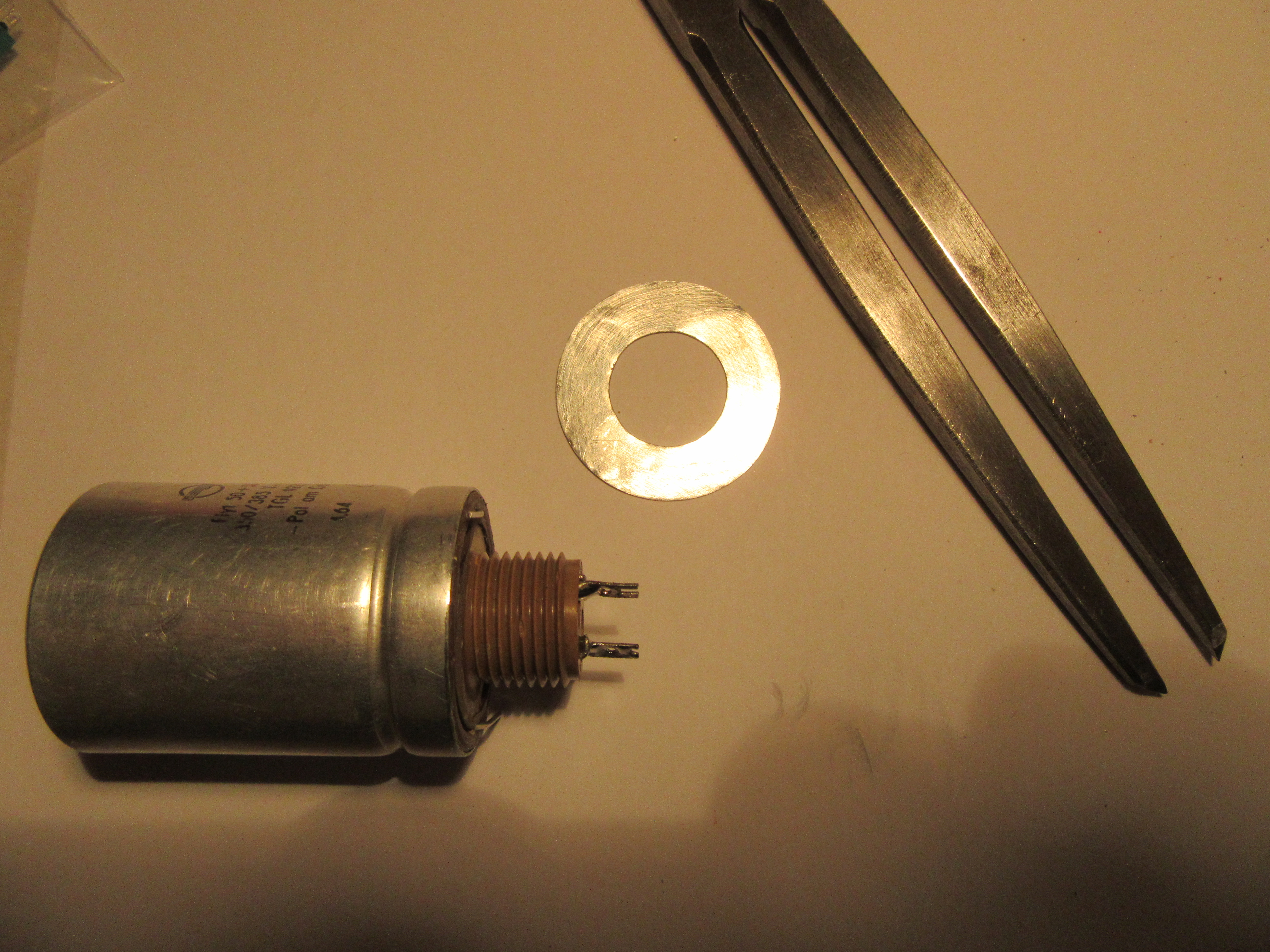
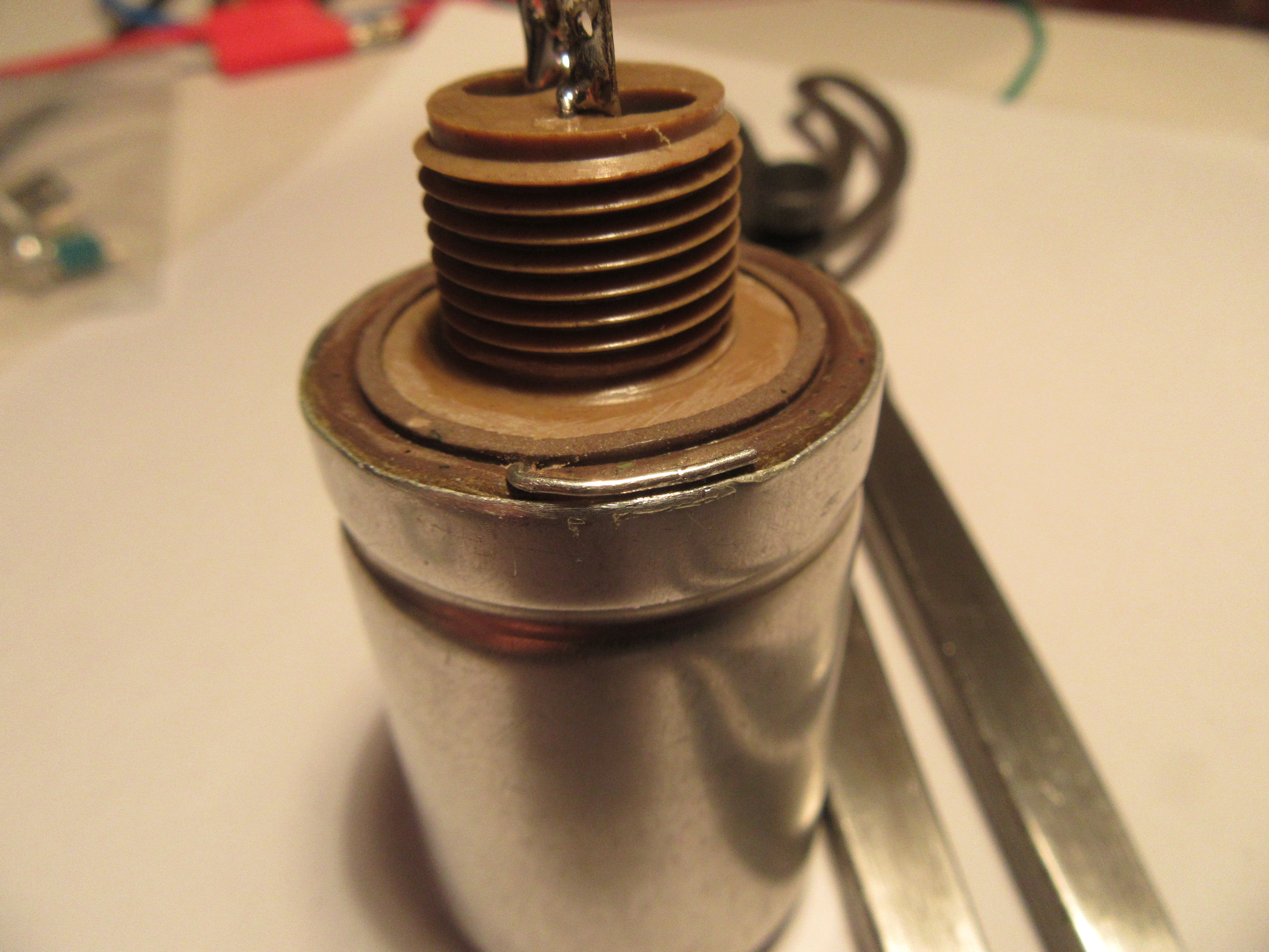
Open electrolytic capacitor and replace inside
I present this process here as a small picture story. In fact, the electrolytic capacitor was as dry as dust inside as suspected. As a safety note, I would like to add that gloves and a respirator should be worn for the work. Normally, the electrolytes from standard electrolytic capacitors are non-toxic, but whether in the 50s and 60s really value was placed on non-toxicity, I dare to doubt.
Elko reform
In general, devices with a mains connection that have not been switched on for a very long time should not be put back into operation so easily. Often the power supply electrolytic capacitor then causes a short circuit, which leads to various subsequent errors. The electrolytic capacitor must be reformed, for which there are two basic possibilities. You can do this in the device or you can remove the capacitor.
Reform in the device
If someone uses the procedure described here himself, then expressly at your own risk. I have already done this several times with success, but that does not mean that it always works. The procedure is simple and relies on the fact that old devices are quite robust and a short circuit does not harm the power supply. Every day, the power is turned on a little longer. After that there is a resting period in which the oxide layer in the electrolytic capacitor can build up again.
- day 1: Switch on for 5s
- days 2-3: Switch on for 10s each
- days 4-7: switch on for 20s each
- from day 8: double the time every day
For very old devices, i.e. older than 50 years and for particularly careful procedures, the phase days 2-3 must be extended to considerably more days, I would suggest up to 2 weeks.
Reforming with high voltage power supply
My preferred method is forming with a high voltage power supply with current limiting. This is a very safe method if you monitor the leakage current and slowly increase the voltage accordingly. The duration of the process goes from a few hours to several weeks. It depends entirely on the age and design of the capacitor. The voltage is slowly increased while taking care not to exceed the maximum leakage current.
My guideline values for the maximum leakage current are:
- 50µA per µF for 350V capacitors
- 100µA per µF for 500V types
For capacitors that are from the 40’s or early 50’s, the leakage current can go as high as three times that value. The important thing is that at some point a stable value is established.
Of course, a high voltage power supply and a current meter with 1mA measuring range is not available to everyone. Here I have found a tutorial, how it is also easier:
Formieren_alter_HV-Elkos

Quelle: http://www.el-me-se.de/old/pdf_files/Formieren%20alter%20HV-Elkos.pdf
Hast Du schon einmal ausprobiert, das alte Gerät an einen Stelltrafo anzuschließen und diesen von nahe Null extrem langsam hochzudrehen?
Hallo Stefan,
das habe ich tatsächlich schon mal probiert. Auf jeden Fall ist das eine gute Lösung, die auch noch den Vorteil hat, dass man nichts ausbauen oder löten muss. Nachteil ist, dass man manuell nachregeln muss. Außerdem könnte einem der Elko trotz aller Vorsicht um die Ohren fliegen, da man im eingebauten Zustand schwer den Leckstrom prüfen kann. Ich würde das nur für Geräte verwenden, die so ca. ab 1970 gebaut wurden. Bei älteren Geräten würde ich auf Nummer Sicher gehen.
Viele Grüße,
Uwe
Hallo Uwe!
Ich bin über Deine Seite gestolpert, auf der Suche nach einer Lösung für einen Hochspannungskondensator einer Mikrowelle. Diese scheint (?) es nicht mehroder kaum in der Bauform wie in den Neunzigern zu geben, mit eiem M12 Gewindstift. Also muß das ordentlich im Gehäuse irgendwie bewerkstetelligt werden. Warum keine neue MW? Nun, das Maß gibt es nicht mehr. Einerseits und andererseits hat Miele damals auch schon mit einem Einbaurahmen drumherum getrixt, um auf ein (teures) Einbaumaß zu kommen. Ich habe entweder ein totes Gerät in der Küche, oder ein Loch. Oder man kauft eine neue Küche. Das will ich noch vermeiden.
Nun zu Deinem Projekt. Ich habe ein Fabel für alte Dinge (im historischen Sinne, die Miele-Küche gehört nicht dazu). Diese Lösung als (Nichtelektroniker) imponiert mir. Ich empfinde das als sensibelen respektvollen Umgang mit solch einem Stück Technik.
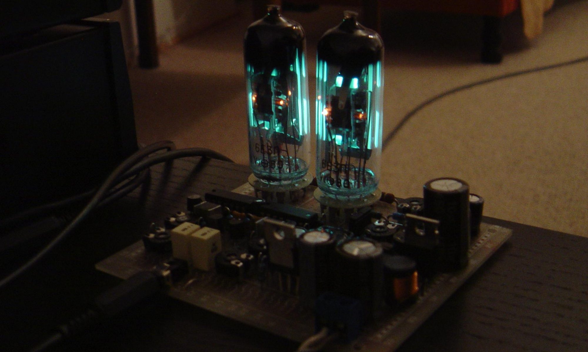
Als Kind, das sehe ich gerade geistig vor mir, hat mich das magische Auge unseres Röhrenradios unglaublich fastziniert.
Also viele Grüße Peter