Recently, my father wanted to give away his complete photo equipment, which had accumulated over the last 50 years. Fortunately, I could still intervene in time and now some dings of it will remain a little longer in the family. “Complete photo equipment” sounds like a lot of stuff now, but it was just a not quite full jute shopping bag with three cameras, as many flashes, all kinds of lenses, two light meters, extension rings, etc. pp. Everything is in a state of disrepair after a long time of use and needs some attention.
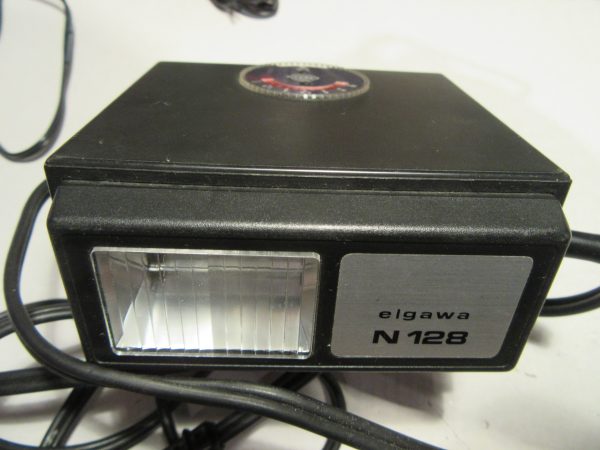
First I chose something simple and went for one of the three flash units, an “Elgawa N128”.
Very important for all who want to get old devices out again and put them into operation: NEVER simply turn on an old unit that has not been in use for 10-20 years or more. Almost certainly the filter electrolytic capacitor in the power supply will be degenerated and lead to a short circuit. In other words, after a short time the electrolytic capacitor will go bye-bye with a bang and there will be a lot of work for the restorer. Of course, this applies primarily to devices with a mains connection.
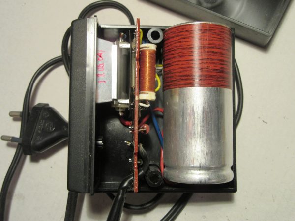
So I opened the device first.
The inner workings are clearly arranged with few components.
Most of the components are from 1983, the flash itself from 17.5.1984.
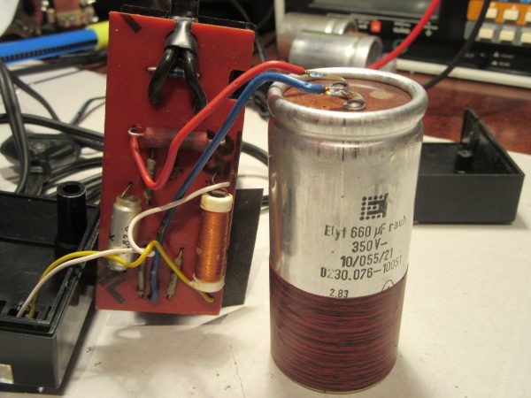
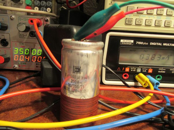
I have desoldered and reformed the electrolytic capacitor. I have dedicated a separate article to the topic of restoring and reforming electrolytic capacitors. Here only so much to the topic: Without voltage the oxide layer in the electrolytic capacitor slowly degrades. The process is reversible as long as an electric field is applied again. Since the rebuilding of the oxide layer is an electrochemical process, it takes some time. I do this with a short circuit proof high voltage power supply and control the leakage current through the electrolytic capacitor while gradually increasing the voltage. After a few hours or days, the electrolytic capacitor is ready to go again. In this case, it only took about 4 hours for the leakage current to settle below 400µA at nominal voltage of 350V, an excellent value.
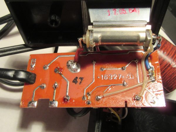
In the meantime, I took a closer look at the circuit board. Obviously it was a misproduction, which was corrected manually. A conductor was drilled out and a wire bridge was installed. Nowadays this would be electrical scrap. Another interesting thing is the fuse. Between the two solder joints on the lower left, a very thin wire is installed as a fuse. This is cheap, but unfortunately very sensitive to touch. I promptly broke the wire while cleaning it and had to extend it on one side with a small piece and solder it back on.
I have also drawn the circuit diagram while waiting for the newly formed electrolytic capacitor, for the interested electronics engineer. I find it interesting that the exposed trigger contacts are directly connected to the mains voltage via two 2.2 Megohm resistors, i.e. without galvanic isolation. This would certainly be solved differently today.
After reassembly at the end, everything worked wonderfully again. The flash is far more powerful than anything built into cameras. The decent sized capacitor is discharged through the flash tube with no current limit. This gives a real bang every time, which I still remember from my childhood and easily illuminates rooms up to 9m away. The 180 ohm / 5 watt series resistor has to cope with just under 300W for a short time during charging and then always gives off a tiny wisp of smoke. This is not threatening and overall the device is quite robust with the disadvantage that it always has to be charged at a power outlet after every single flash.
Update 24.05.2023
The latter disadvantage could be circumvented with an additional device, the inverter BZG1, which was also produced by VEB Elgawa Plauen (Vogtl.). This portable device generated 220V from 4 mono cells to charge the flash. A kind reader sent me the circuit diagram taken from an original, many thanks for that.
BZG1_Transverter_02

Quelle: Christian Seifert

Danke für den Schaltplan des Elgawa N128. Bei mir war der R1 durch zu häufige Blitzfolge am Netz durchgebrannt.
Vielleicht sollte man noch darauf hinweisen, dass die Sicherung ein hauchdünner Draht auf der Platine ist, den man leicht übersieht und zerstören kann.
Sehr gute Beschreibung!
Herzliche Grüße!
Hallo Stefan,
toll, dass der Beitrag hilfreich war. Einen kurzen Absatz über die unkonventionelle Schmelzsicherung hatte ich geschrieben. Auch ich hatte die aus Versehen kaputt gemacht. 😮
Viel Spaß noch beim Reparieren und alles Gute!
Uwe
Danke für die Dokumentation der Innenschaltung des N128. Das Ding ist echt kräftig.
Dazu gab es ja zu DDR-Zeiten das BZG1 für die netzunabhängige Nutzung. Damit konnte man den Blitzkondensator mit vier R20-Zellen laden. Mich ärgerte, dass nirgends im Web der Schaltplan dazu zu finden war. Deshalb habe ich mich mal drüber gemacht, den von meinem Gerät abzunehmen. Falls Sie möchten, sende ich Ihnen den Plan gerne zu, er wäre sicher eine gute Ergänzung Ihrer Dokumentation.
Hallo Herr Seifert ,
würde mich sehr freuen wenn Sie mir den Schaltplan des BZG1 zusenden würden . Den Schaltplan des N128 habe ich im Netz gefunden .
Mit freundlichen Grüßen
A. Stade
Hallo Herr Seifert,
dem Wunsch von Herrn oder Frau Stade schließe ich mich an und kann auch gern vermitteln.
Danke und viele Grüße,
Uwe