Flash Elgawa N128 restoration

Recently, my father wanted to give away his complete photo equipment, which had accumulated over the last 50 years. Fortunately, I could still intervene in time and now some dings of it will remain a little longer in the family. “Complete photo equipment” sounds like a lot of stuff now, but it was just a not quite full jute shopping bag with three cameras, as many flashes, all kinds of lenses, two light meters, extension rings, etc. pp. Everything is in a state of disrepair after a long time of use and needs some attention.

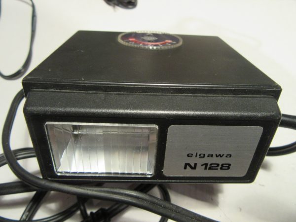
First I chose something simple and went for one of the three flash units, an “Elgawa N128”.

Very important for all who want to get old devices out again and put them into operation: NEVER simply turn on an old unit that has not been in use for 10-20 years or more. Almost certainly the filter electrolytic capacitor in the power supply will be degenerated and lead to a short circuit. In other words, after a short time the electrolytic capacitor will go bye-bye with a bang and there will be a lot of work for the restorer. Of course, this applies primarily to devices with a mains connection.

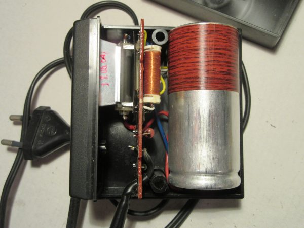
So I opened the device first.

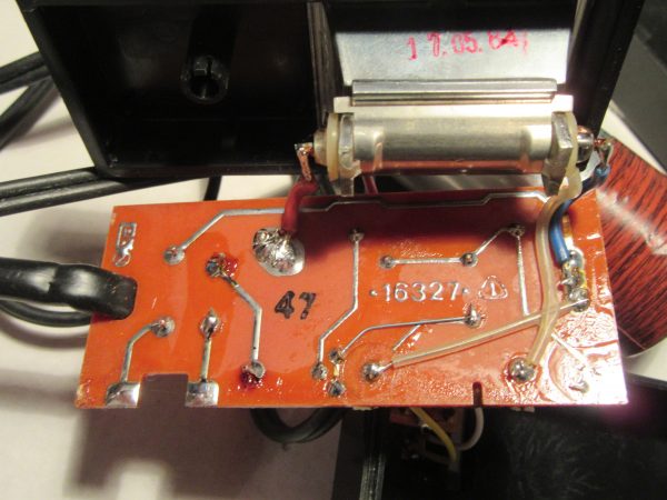
The inner workings are clearly arranged with few components.

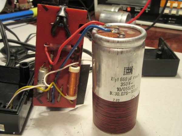
Most of the components are from 1983, the flash itself from 17.5.1984.

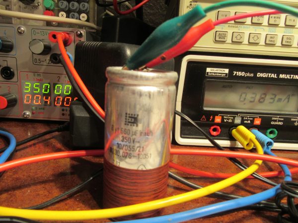
I have desoldered and reformed the electrolytic capacitor. I have dedicated a separate article to the topic of restoring and reforming electrolytic capacitors. Here only so much to the topic: Without voltage the oxide layer in the electrolytic capacitor slowly degrades. The process is reversible as long as an electric field is applied again. Since the rebuilding of the oxide layer is an electrochemical process, it takes some time. I do this with a short circuit proof high voltage power supply and control the leakage current through the electrolytic capacitor while gradually increasing the voltage. After a few hours or days, the electrolytic capacitor is ready to go again. In this case, it only took about 4 hours for the leakage current to settle below 400µA at nominal voltage of 350V, an excellent value.

In the meantime, I took a closer look at the circuit board. Obviously it was a misproduction, which was corrected manually. A conductor was drilled out and a wire bridge was installed. Nowadays this would be electrical scrap. Another interesting thing is the fuse. Between the two solder joints on the lower left, a very thin wire is installed as a fuse. This is cheap, but unfortunately very sensitive to touch. I promptly broke the wire while cleaning it and had to extend it on one side with a small piece and solder it back on.

I have also drawn the circuit diagram while waiting for the newly formed electrolytic capacitor, for the interested electronics engineer. I find it interesting that the exposed trigger contacts are directly connected to the mains voltage via two 2.2 Megohm resistors, i.e. without galvanic isolation. This would certainly be solved differently today.

After reassembly at the end, everything worked wonderfully again. The flash is far more powerful than anything built into cameras. The decent sized capacitor is discharged through the flash tube with no current limit. This gives a real bang every time, which I still remember from my childhood and easily illuminates rooms up to 9m away. The 180 ohm / 5 watt series resistor has to cope with just under 300W for a short time during charging and then always gives off a tiny wisp of smoke. This is not threatening and overall the device is quite robust with the disadvantage that it always has to be charged at a power outlet after every single flash.

Update 24.05.2023

The latter disadvantage could be circumvented with an additional device, the inverter BZG1, which was also produced by VEB Elgawa Plauen (Vogtl.). This portable device generated 220V from 4 mono cells to charge the flash. A kind reader sent me the circuit diagram taken from an original, many thanks for that.

BZG1_Transverter_02
Quelle: Christian Seifert
 

Receive updates directly in your inbox

Loading


Test oscilloscope tube Telefunken O7S1

First, I have to give a quick heads up: this post is a little longer than usual but that’s how it is with a hobby. You have a plan, you learn new things in the middle of it, and you expand a project piece by piece. A hobby is not about efficiency, but about making something “beautiful” and being satisfied at the end. So it doesn’t take long to add a few extra weekends of tinkering to something that should only take a few hours…
From the planned test of the O7S1 had resulted in the course of the time also these points:

  • Sawtooth generator, test setup and simulation with PSpice
  • Amplifier for X- and Y-deflection with double triode 6N2P
  • Overall circuit for a mini oscilloscope

But now let’s get started with the article.


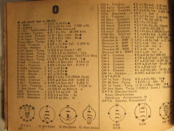
Recently I rebuilt an old oscilloscope “Picoscope”. Among some other things the cathode ray tube was missing. In the original device a B7S1 from VEB Funkwerk Erfurt (part of RFT) is installed. The designators of such tubes are usually composed like in this case: A letter followed by the screen diagonal and the more exact designation. In this case, B7S1 probably stands for picture tube, 7cm diagonal, system 1. After a short internet search for this spare part, I didn’t find a B7S1, but an O7S1 for a relatively low price. A further search in my tube codex from 1948
Röhren-Codex 1948
“Röhren-Codex” 1948

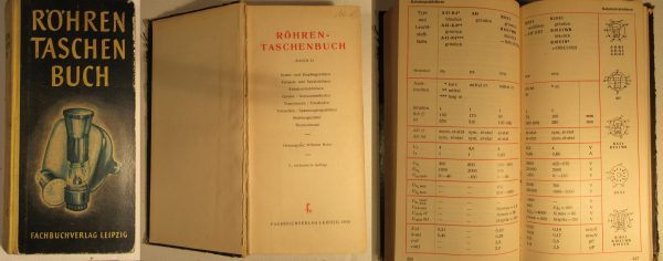
and at radiomuseum.org revealed that an O7S1 is a pre-1945 Telefunken picture tube model. It has the same heater voltage and apparently the same socket circuitry as a B7S1. Further data on the O7S1 was not available. Unfortunately, my “Röhren-Taschenbuch” from 1958 from the “Fachbuchverlag Leipzig” does not contain the B7S1 yet.

Röhren-Taschenbuch Band II, 1958
“Röhren-Taschenbuch” Volume II, 1958

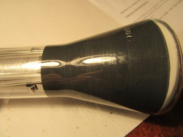
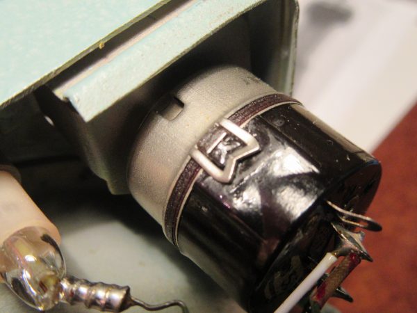
However, the similarity between the two tubes led me to believe that the B7S1 from RFT from the 50s is a compatible replica of the Telefunken tube from the 40s. So I bought it without further ado and after a few days the tube arrived undamaged. The first sight was good. Externally and mechanically everything was apparently in order, the contacts had not been in a socket for ages. This can be seen quite easily with a magnifying glass on corroded but not scratched contacts. Also the Telefunken logo and the designation are still held diagonally against the light, quite good to see. The silver inscription O7S1 is applied from modern times with one of these special pens.

O7S1 Bezeichnung und Telefunken Logo
O7S1 designation and Telefunken logo

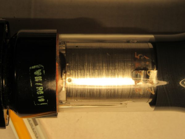
On the base itself was the original imprint V II / RÖ 19. It occurred to me briefly whether it might not be Roman seven, but V Roman two or V2. Probably, however, it means assembly 7 / tube 19. If anyone knows which device it could be, I absolutely ask for a message.

O7S1 Sockel Detail
O7S1 socket detail

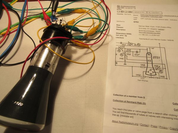
Since I still have an original Picoscope EO1/7, I could put the tube in there and do a quick test. But everything remained dark. Nevertheless, I did not give the online dealer a bad rating at first, but set up a test circuit. Very helpful was the page of Burkhard Kainka, on which beside many basics as well as small and large tinkering projects also a test circuit for a mini-oscilloscope is published. At this point a big thank you from me to the operator of the site for the work to publish all this.


Back to the test circuit: During the setup it quickly became clear that the sockets of the two tubes B7S1 and O7S1 are rotated by 180° and after a short time I could see that the tube basically works.

O7S1 Erster Test
O7S1 First test

What followed was a few weekends of tinkering. First I found out that grid 1 has no function anymore. This means that direct brightness control is no longer possible. This is not so much a problem, because you can also regulate the brightness with the anode voltage. However, it may also affect the focus, and probably the tube will no longer have the performance it had in its original state. Nevertheless I tried to develop the best possible circuit. Basis was as described above the test circuit of Burkhard Kainka.

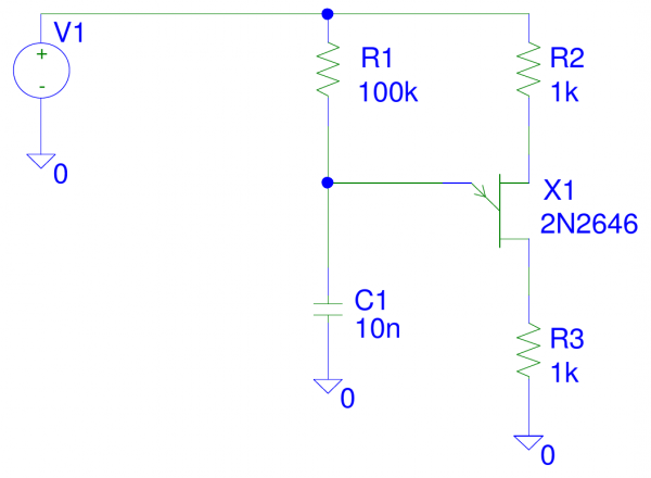
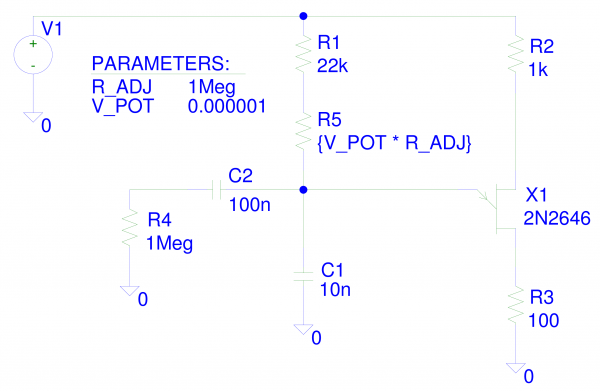
First I tried to improve the X-deflection. Ideal is a sawtooth generator, which has a linear voltage rise and very fast fall. However, the original flip-flop circuit with a glow lamp gives an exponential voltage waveform. You can see this very clearly in the oscillogram in the article by Burkhard Kainka, the curve is compressed on the right. My idea should be as simple but a bit better and finally I experimented with a sawtooth generator with a unijunction transistor (UJT), whose basic circuit is quite simple.

Schaltbild PSpice Simulation Sägezahngenerator mit UJT 2N2646 erster Versuch
Schematic PSpice simulation sawtooth generator with UJT 2N2646 first try

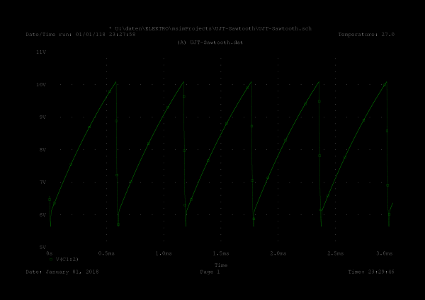
At the emitter a sawtooth can be taken, which is already a bit more linear than a toggle circuit with glow lamps. Of course it is again the charge curve of a capacitor or an e-function. But here we are only in the lower range. A simulation with PSpice shows the expected, a not quite linear increase.

PSpice Simulation Sägezahngenerator mit UJT 2N2646, erster Versuch
PSpice simulation sawtooth generator with UJT 2N2646, first try

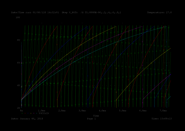
Since the frequency should be variable, I have inserted a resistor into the circuit, which is changed during the simulation via a parameter. With PSpice this is done by placing a global parameter on the worksheet, in this case V_POT. Several simulations are then run and this parameter is changed. I have chosen steps of 0.2 between zero and one. Via C2 and R4 the load of the generator is represented.

Schaltbild PSpice Simulation Sägezahngenerator mit UJT 2N2646
Schematic PSpice Simulation Sawtooth Generator with UJT 2N2646

Again, the simulation did not reveal any surprises. However, it was quite difficult to get the convergence problems under control with PSpice. This is especially problematic when simulating oscillators and one has to experiment with some simulation parameters until everything runs error-free to the end.

The frequency is adjustable within wide limits, we now have an excellent sawtooth generator for the X-deflection.

PSpice Simulation Sägezahngenerator mit UJT 2N2646, 7.5ms
PSpice simulation sawtooth generator with UJT 2N2646, 7.5ms

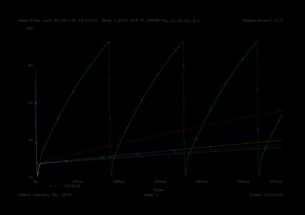
And another clip of the first half millisecond.

PSpice Simulation Sägezahngenerator mit UJT 2N2646, 500µs
PSpice simulation sawtooth generator with UJT 2N2646, 500µs

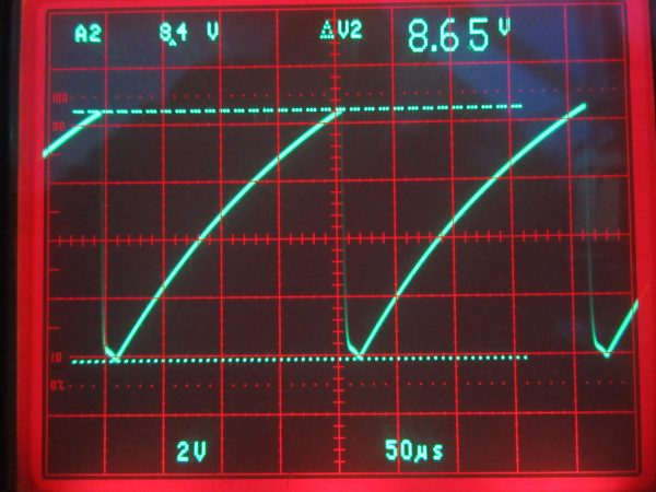
At the end I made an oscillogram of the built up sawtooth generator at minimum frequency, so it should look like the green curve. And voila it looks pretty similar. The amplitude is a bit higher and the frequency is a bit lower. I blame this on the component tolerances.

Oszillogramm Sägezahngenerator mit UJT 2N2646
Oscillogram sawtooth generator with UJT 2N2646

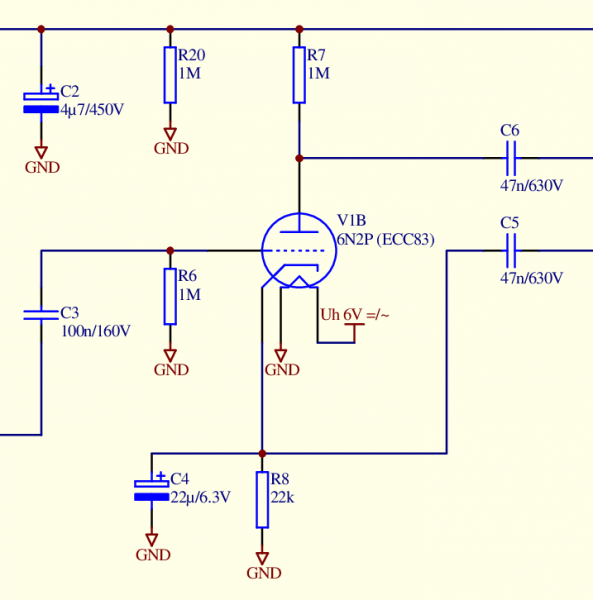
The sensitivity of the O7S1 is rather moderate. The exact value is not known to me. My tests showed about 50V/cm for the X- and 40V/cm for the Y-deflection. This left the next task to be solved, to amplify the signal by a factor of 25 to 30. True to style I chose a triode. The high voltage for the picture tube is available anyway, so the use of another tube does not mean a big additional effort. As a triode with high amplification an ECC83 is a good choice. Because of the high price of the ECC83 I chose the very similar 6N2P or 6H2П, which is still manufactured in Russia. As circuit a standard amplifier circuit for triodes is used. Here is the section of the overall circuit diagram of the mini-oscilloscope.

Schaltbild Verstärker mit Triode
Circuit diagram amplifier with triode

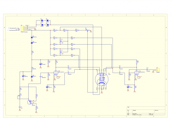
The second system of the double triode was used for the Y-amplifier, which is constructed identically to the X-amplifier. Some of the deflection plates must have a higher potential than the anode to be able to shift the X and Y origin over the whole visible range. This function is realized by some voltage dividers and potentiometers (R9 to R19 and P2/P3). With potentiometer P4 the focus is set. With this the mini-oscilloscope worked reasonably well and I was satisfied.

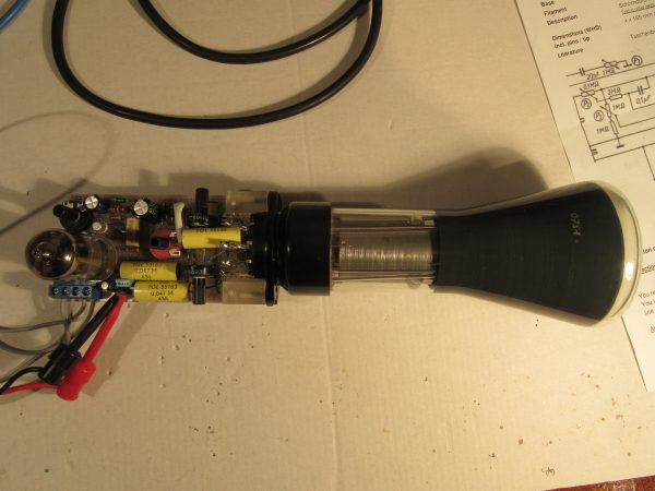
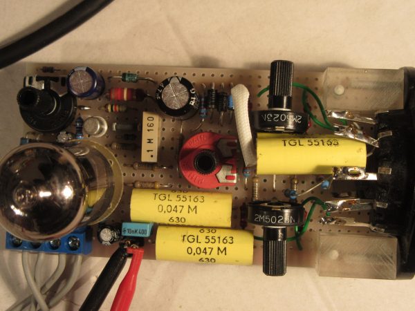
Finally the complete schematic, a photo gallery and a short video.

Vollständiges Schaltbild
Complete schematic


Mini-Oszilloskop komplett
Mini oscilloscope complete


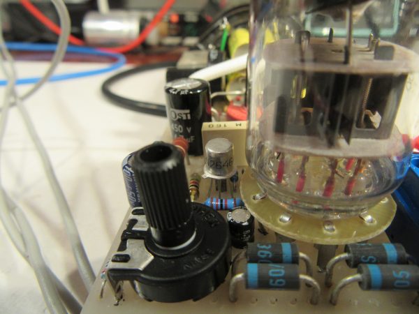
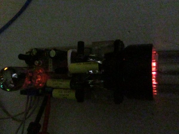
Mini-Oszilloskop Elektronik
Mini Oscilloscope Electronics


Sawtooth generator with unijunction transistor 2N2646


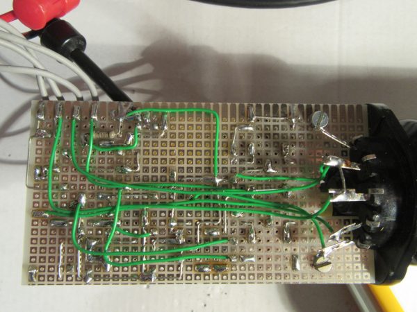
Mini-Oszilloskop Elektronik von unten
Mini oscilloscope electronics from below

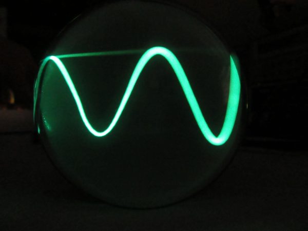
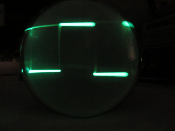
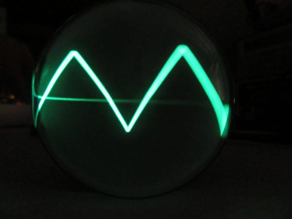
Sine, square and triangle signals approx. 2kHz from my function generator.

Sinus Rechteck Dreieck

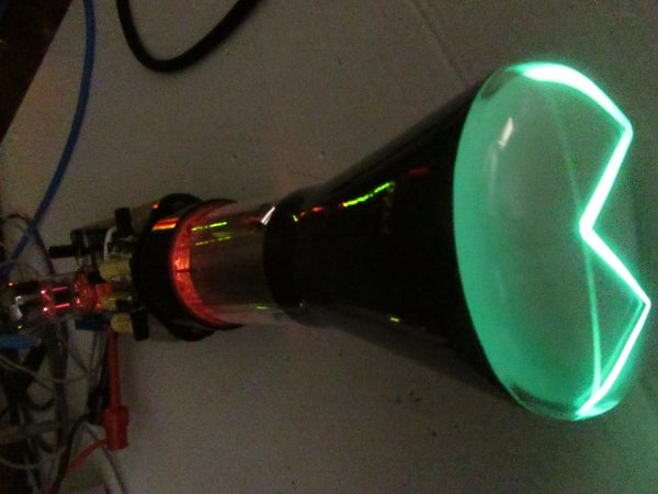
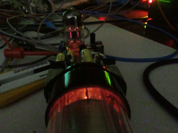
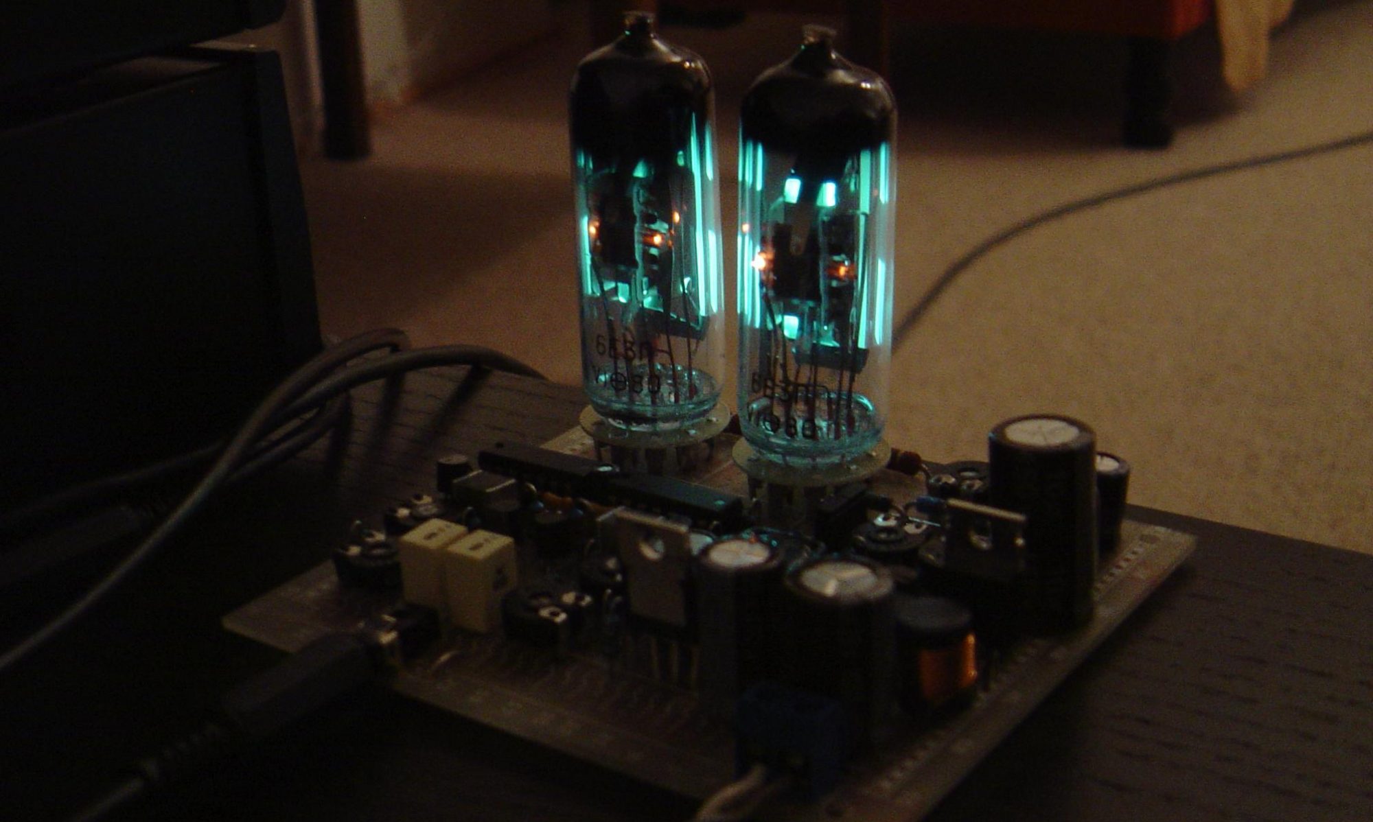
The tubes glow.

This is what the whole thing looks like live, fed from the function generator.


Receive updates directly in your inbox

Loading


Restoration oscilloscope Picoskop EO1/7

A small oscilloscope, a Picoscope EO1/7 is in my possession for a long time. When I bought it maybe 20 years ago for nostalgic reasons for little money, I got an extra chassis as a spare parts donor with it. This chassis was rusted, bent, some parts were missing or broken. Of course, there was no tube left either.

During a cleanup this spring, this chassis was supposed to go into the scrap. Before I had the heart to do that, I made an inventory:

  • all tubes incl. the picture tube are missing
  • selenium rectifier missing
  • no front panel and no case
  • rust and dirt on all parts
  • potentiometer with power switch, mechanics bent, Bakelite switch housing broken
  • potentiometer rear cover missing
  • fuse holder incomplete
  • MP condenser one terminal broken, oil leaking out
  • wiring harness partly removed by brute force
  • one ceramic tube socket broken
  • two resistors destroyed
  • few capacitors missing

But the power transformer, the filter choke and a smaller high voltage transformer were apparently still intact. Furthermore, both rotary switches for X and Y were OK. These are quite good conditions for a rebuild I thought. Unfortunately I didn’t take a picture of the original condition. It really looked like a pile of junk.

The beginning

First, I disassembled the unit as much as possible, cleaned it properly and partially derusted it. After derusting, I sealed the power transformer with an alkyd resin lacquer. Basically you should use a high voltage insulating varnish for this. Since this is not so easy to get privately, it does also e.g. a good colorless boat varnish as in my case.

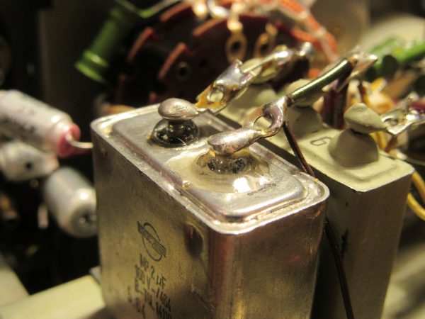
The next step was to repair the defective components. The leaking MP capacitor got a new terminal lug, luckily a small piece of the old terminal was still sticking out. After that, the thoroughly degreased connection was sealed with epoxy resin.

I also glued the broken tube socket with epoxy resin. In the picture you can see that behind one of the two replaced resistors.

It is important to use the “normal” epoxy resin for bonding. This is resin and hardener, which you usually have to mix in a ratio of 100:60 to 100:40. The curing time is 24 to 48 hours. There are also all kinds of fast-curing epoxy-based adhesives. In my experience, however, these do not adhere as well to ceramics and Bakelite.

Bakelite is the keyword for the next repair, the potentiometer with the power switch. Here I could straighten the mechanics again. Fortunately, all fragments of the switch housing were available. Bakelite can also be glued excellently with low viscosity epoxy resin. Afterwards, the glued area is usually more stable than the rest. After cleaning, lubrication and contact care with Neo-Ballistol, the potentiometer works like new again.

Lastly, I made a new rear cover for the second defective potentiometer. In contrast to the original, I made this from aluminum instead of sheet steel. Thanks to my electromechanical training in the 80s, I can do such work relatively precisely.

This saved the components that could be saved. The function of the two defective pots is completely restored and because of the presumably better lubrication, the expected service life is possibly also longer than with the original.

Spare parts

Some spare parts I had to order. The fuse holder is a standard model from the GDR and still relatively easy to find on the Internet. From the tubes ECF82 I was able to purchase a lot of 8 pieces very well preserved copies from Telam at a good price. It was important to me that all tubes are one make. I think this is a good idea for metrology.

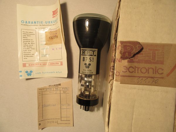
A bit more difficult was to get a cheap picture tube, the B7S1. The offered ones were too expensive for me and that with uncertain function. By chance, I came across an O7S1, compared the base scheme and characteristic values and was of the opinion that the O7S1 is a direct predecessor of the B7S1 from the time before 1945. In the end, I had to find out that this is not so. The base is turned by 180°, the cathode is not led out individually and the three grids have also somewhat different functions. I described the test of this tube in a separate blogpost. So in the end I had to look for a B7S1 and with some luck I found a new and original packed one, even the warranty certificate was still there.

B7S1 OVP, Kassenbon und Garantieurkunde

Reconstruction

First I dedicated myself to the power supply. Also to test first if everything is ok with the hard to repair transformers. Unfortunately the selenium rectifiers were missing and I had to replace these two two-way rectifiers then by four diodes 1N4007 in bridge circuit.

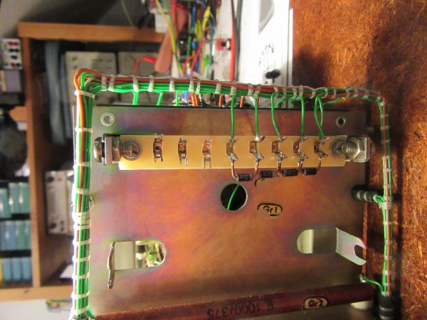
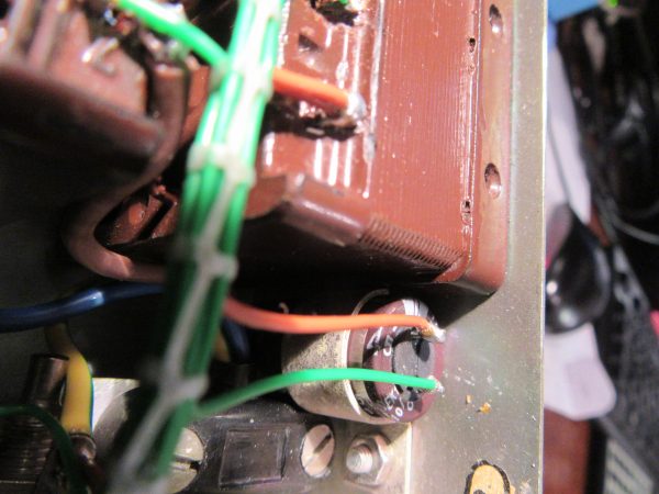
Also, the wiring harness of the power supply was completely missing. I rebuilt it pretty much original. However, instead of the double-wound wire, a modern alternative with ETFE insulation was used. I dedicated a whole blogpost “The wiring harness” to this wiring variant. Of the two electrolytic capacitors in the power supply, one axial 10µF/350V was unsalvageable due to a broken connection directly at the case. In its place, a modern radial variant with 450V dielectric strength is now doing its job.

EO7/1 ausgetauschter Elko

I reformed the 50µF/350V cup capacitor within two weeks. This worked wonderfully, at nominal voltage it had only 80µA leakage current at the end. I have dedicated a whole article to the forming of electrolytic capacitors.

Unfortunately I did the first test of the power supply without load. Because of this and the lower voltage drop of the new rectifier bridge made of silicon diodes, the anode voltage had about twice the nominal value at no load. It went poof briefly and the elaborately formed cup electrolytic capacitor was history, really a pity. At least I learned that you should never test power supplies of tube devices without load and how to restore a cup capacitor or how to hide a modern capacitor in it. There will be a post about that here soon, too. After this repair the power supply was complete and worked perfectly.

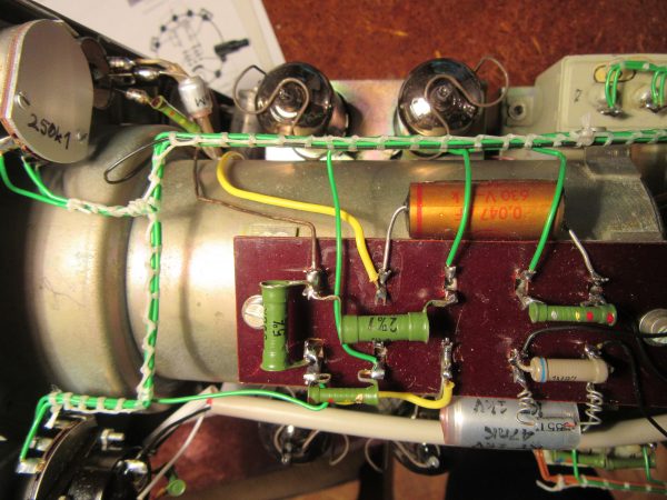
The next step was to restore the other wiring in the unit. In addition, a total of two defective resistors had to be replaced.

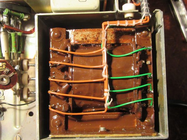
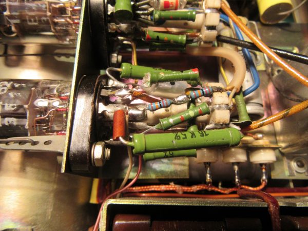
EO7/1 Kabelbaum oben

I have exchanged all paper capacitors for safety reasons and replaced them with film capacitors. I was lucky and was able to replenish my supplies thanks to Markus from Hamburg, who offers many different values at “ebay Kleinanzeigen”. But I felt too sorry for the basically still working paper capacitors to throw them away just because they have a slightly too high leakage current. I documented my attempt to make them fit again in the article “Paper capacitors restore“. This is certainly better than replacing them, since some of the circuitry is designed to handle these higher leakage currents.

Finally, I just put in the four ECF82 tubes and the picture tube, and voila, everything worked flawlessly right away. Now the front panel and the case are missing and at the end the picture tube should show the time in analog form. But that’s a new project.


Receive updates directly in your inbox

Loading

Tie wiring harness

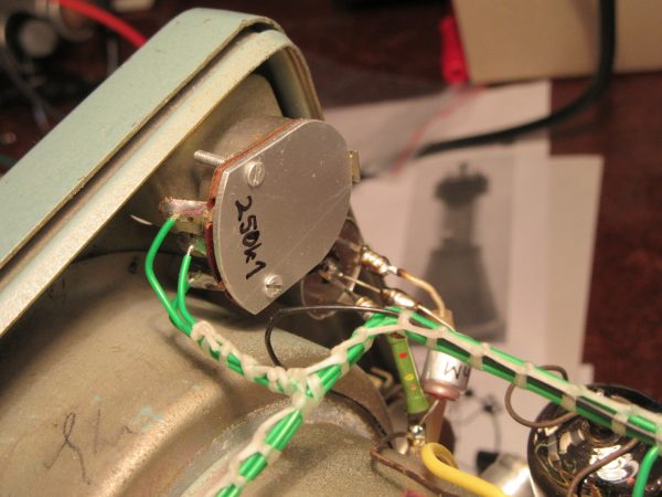
In older devices, for example measurement technology, one often finds cable harnesses tied by hand. This refers to a number of wires that are knotted together with so-called binder twine to form a stable structure. This type of wiring has to be done manually and is therefore very time-consuming. For this reason, it is essentially only used in the aerospace industry today. There are various other ways of producing wire harnesses, such as with cable ties or hoses, etc. But this article is only about the original method with twine. I can imagine that the first wire harnesses were made for telephone exchanges. In any case, the builders of analog switching technology were true masters at crunching wires together.

Basically, cable harnesses have several advantages.

  • The cables are more stable when tied together.
  • Less space is needed for the cabling.
  • Errors during assembly or maintenance are avoided.
  • Overall, the result is very good fail-safety.

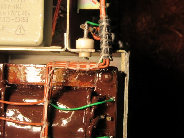
Recently, I restored an old oscilloscope and had to add the missing harnesses again. That was the reason why I dealt with this topic in more detail. Here in the picture you can see the first result and I am overall satisfied with it.

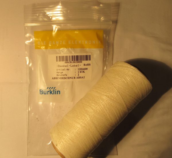
First condition to tie a harness yourself is the right twine. In the past this was a waxed thin natural yarn, probably jute, sisal or flax. In very old telephone switching equipment from the late 20’s or 30’s, which I cannibalized as a kid, you can still find such yarn. Nowadays the material is something like dental floss with a lot of wax. There are only a few suppliers left who supply end users with it. SEGOR-electronics GmbH from Berlin carries it in its assortment under the name “Abbindegarn“. As “Abbindeschur” I bought my supply at Bürklin Elektronik. I also strongly recommend to use a binding twine explicitly made for wire harnesses. Other materials do not work as well and may not be stable over time.

I came across an alternative variant that I still like: durable yarn, probably star twine is dipped in hot beeswax.

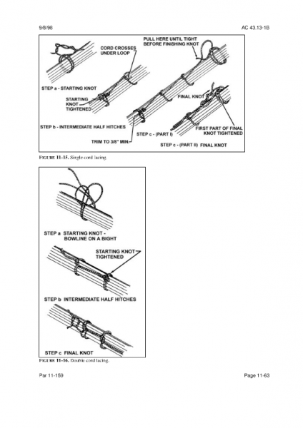
Now the art of knotting is still missing. For an easy start I recommend to follow the guidelines of the FAA, the “United States Federal Aviation Administration”. This has published in its “Advisory Circular” 43.13-1B, Chapter 11 “Aircraft Electrical Systems” instructions that contain only two variants of tying and are so simple and clear.


Quelle: FAA AC 43.13-1B, Chapter 11

Another tip: You can build up the wiring harness in at least two dimensions on a board with small nails. To do this, hammer in a small nail at each bend and at each branch. The wires can then be bent along there, then tied. If the shape of the tree goes into the third dimension, it becomes more difficult and I would wire and bind it directly in the device.

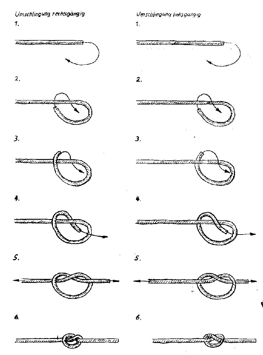
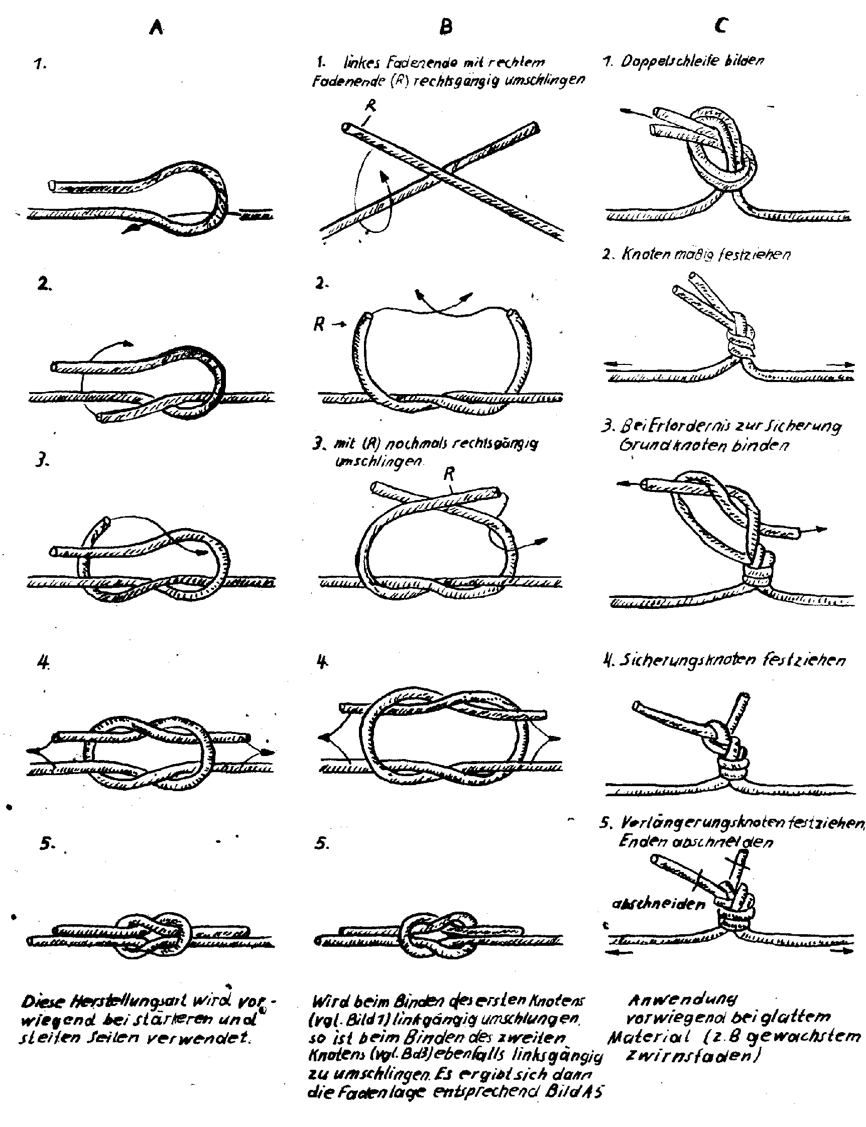
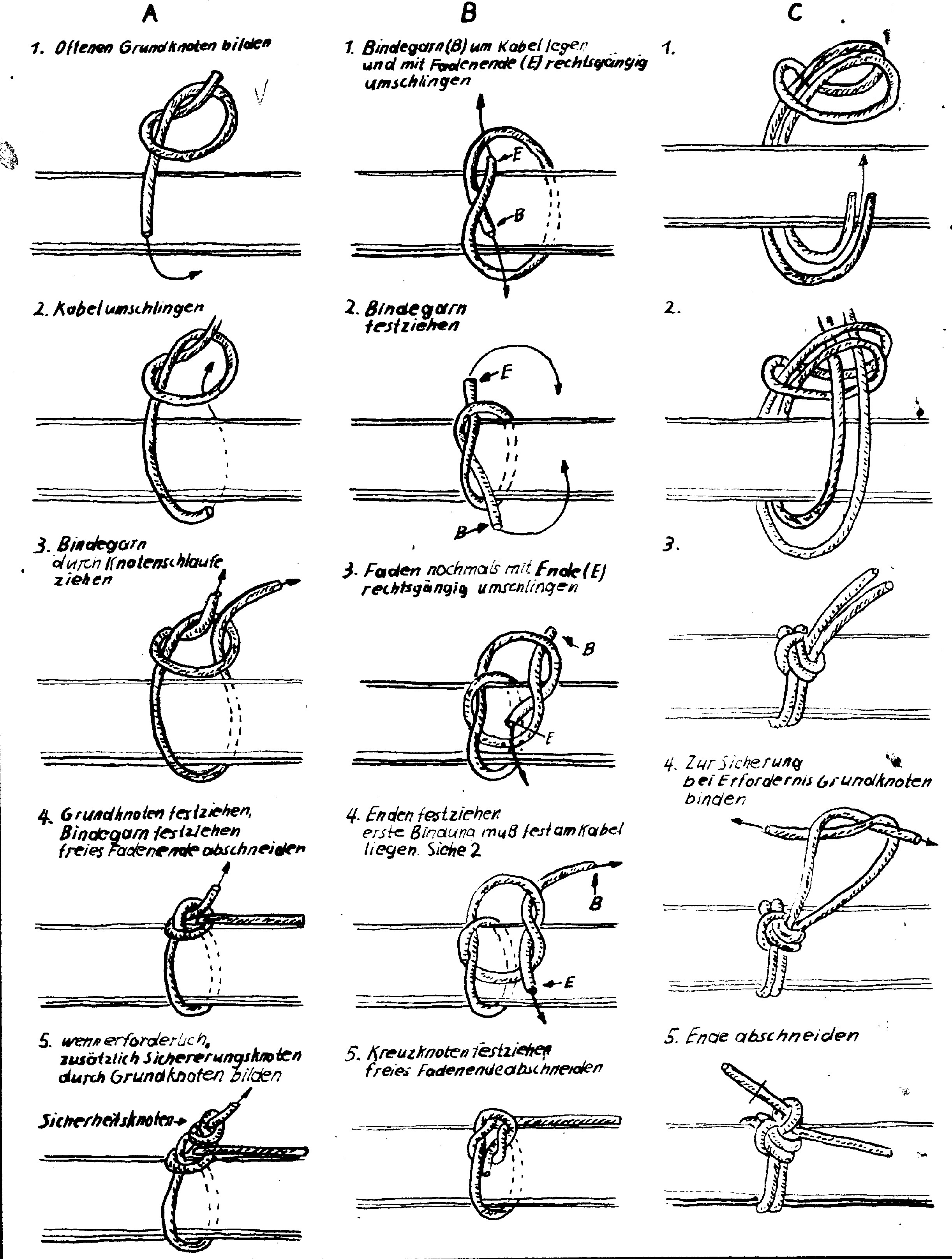
At mikrocontroller.net you can find a thread which also deals with this topic. From this thread come the following multiple variants for node binding. In the end you have to decide for one variant. I decided like this:

  • Initial knot: “Form A mit Sicherheitsknoten”
  • Intermediate knot: “Form B für glatte Oberflächen”
  • Final knot: “Durchschlungener Schlussknoten”

Grundknoten, Quelle: www.mikrocontroller.net
/attachment/49981/Blatt412_Grundknoten.png
Verlängerungsknoten, Quelle: www.mikrocontroller.net
/attachment/49982/Blatt413_Verlaengerungsknoten.png
Anfangsknoten, Quelle: www.mikrocontroller.net
/attachment/49983/Blatt414_Anfangsknoten.png
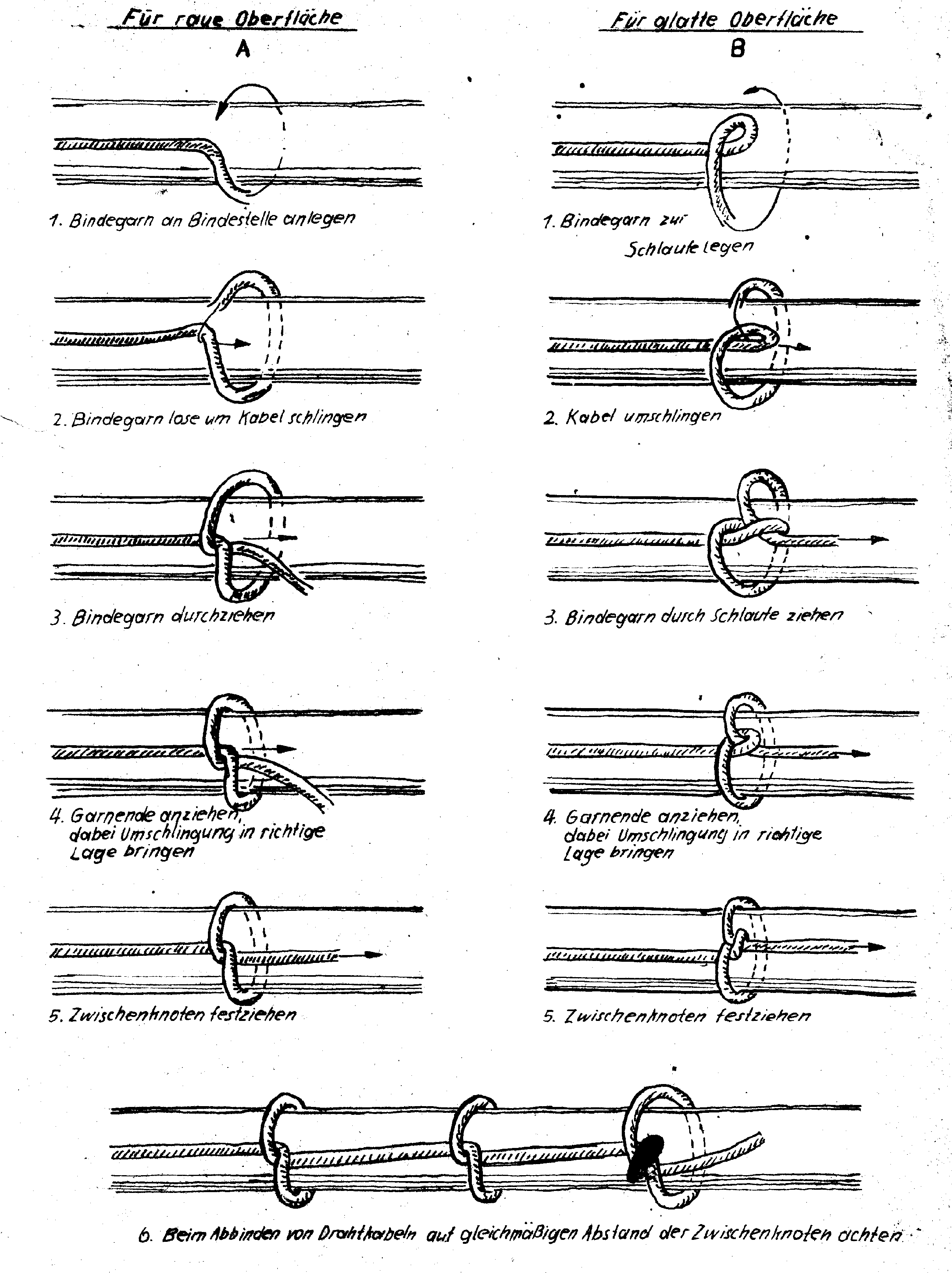
Zwischenknoten, Quelle: www.mikrocontroller.net
/attachment/49984/Blatt415_Zwischenknoten.png
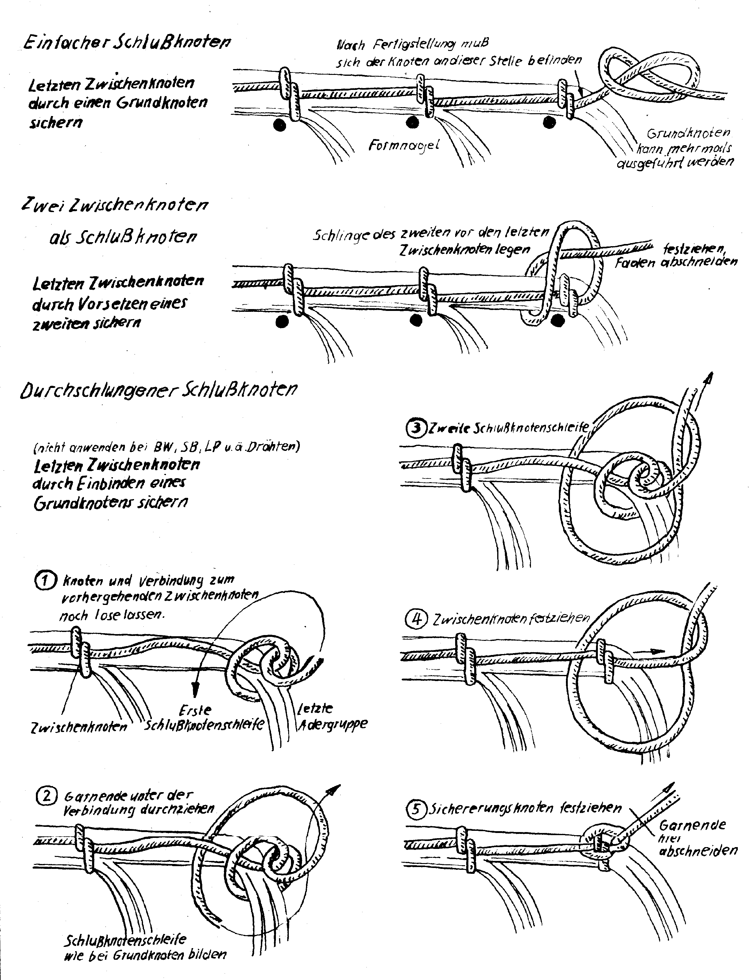
Schlussknoten, Quelle: www.mikrocontroller.net
/attachment/49985/Blatt416_Schlussknoten.png
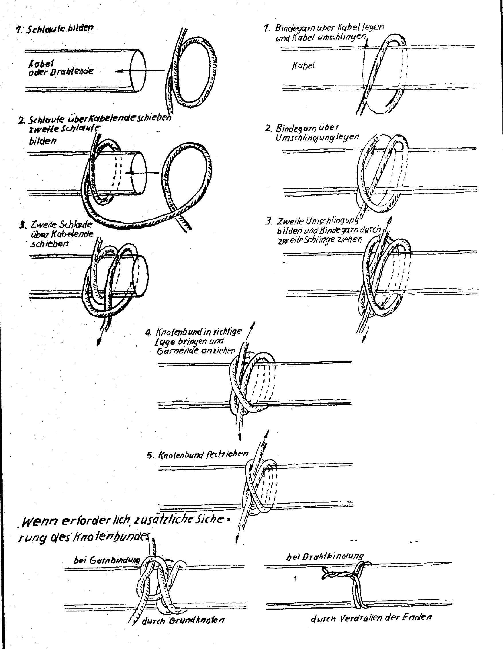
Knotenbund, Quelle: www.mikrocontroller.net
/attachment/49986/Blatt418_Knotenbund.png
The full thread is here: https://www.mikrocontroller.net/topic/64283


Receive updates directly in your inbox

Loading

Paper capacitors restore

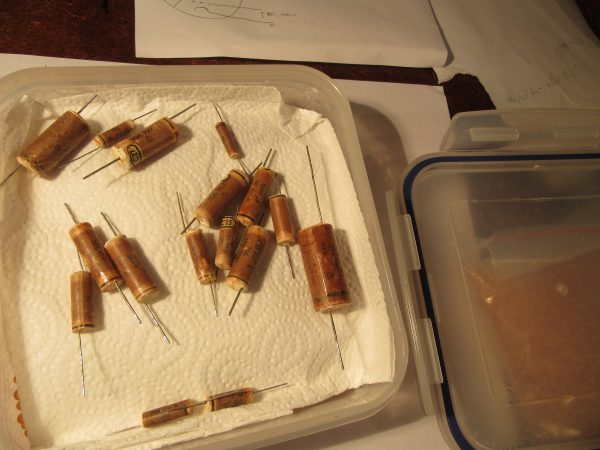
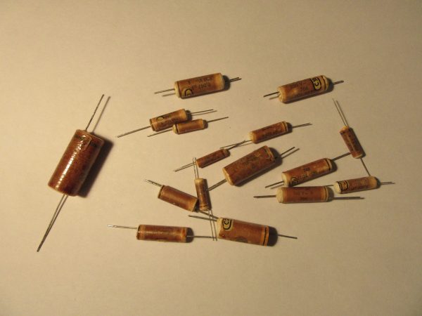
Lately I had to replace almost all capacitors on all GDR tube radios and other equipment from the late 50s to early 70s. The problem is always the paper capacitors of the make “Koweg” (Kondensator Werk Görlitz). Over the years, these capacitors have aged and no longer meet the original specification, especially the leakage current. So far, I have always replaced them with long-life film capacitors. According to my observations, the basic problem of these capacitors is the sealing. At the end faces, this consists of something similar to PUR foam (polyurethane foam). However, this crumbles with time and is no longer present on old and thermally stressed specimens. The second part of the sealant is a varnish that has also become brittle over the years on this series. I suspect it is a nitro varnish. These are the remnants from the last restoration project:

Papierkondensatoren

In the past I simply put these capacitors into the electronic scrap, this time everything should be different. The royal road of any restoration is the preservation of the original substance and from this consideration a plan was born.

My very personal theory is that the paper is hygroscopic. Due to the problem of defective sealing, the paper absorbs moisture over time. Since the paper is insulation and dielectric, a different moisture content will greatly change the properties of the capacitor. So you have to dry the capacitor!

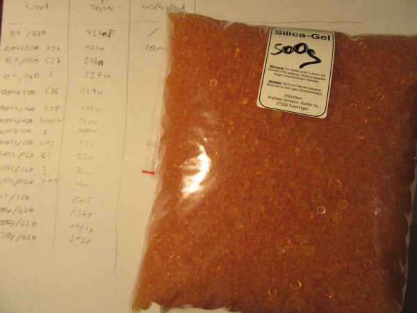
I came up with two viable ways to dry it, in a vacuum or with silica gel in a drying box. Silica gel is a drying agent that is commonly used in closed containers, into which you put the granules and the things you want to dry.

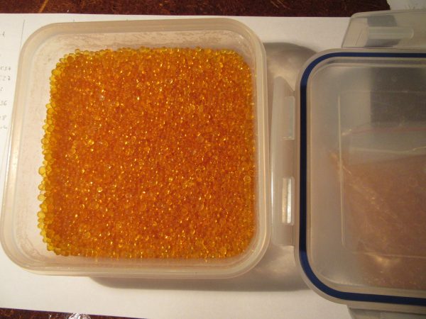
I ordered the granules on the Internet and chose a variant with moisture indicator. In this case, orange means dry, blue means moist. The granules can be regenerated in the oven and reused almost indefinitely.

This granulate now simply goes into an airtight plastic box.

Over it comes a paper towel and then the capacitors on top.

The whole thing now comes over the winter on the heater to further increase the steam pressure. I measured a relative humidity between 5% and 10% in the box.

Next year I will then measure the condensers and see if they have better characteristic values again. In addition, I will then describe here how I do the permanent sealing.


Receive updates directly in your inbox

Loading